Quick turn spherical robot

A spherical robot, fast technology, used in motor vehicles, transportation and packaging, etc., can solve problems such as motion instability, and achieve the effect of simplifying motion control, preventing injuries, and reducing weight

Inactive Publication Date: 2017-07-25
SHANGHAI UNIV
View PDF4 Cites 0 Cited by
  • Summary
  • Abstract
  • Description
  • Claims
  • Application Information

AI Technical Summary

Problems solved by technology

[0004] In order to overcome the motion instability of the existing spherical robot when turning at high speed, the object of the present invention is to provide a fast steering spherical robot that can overcome the rotational inertia force during high-speed travel.

Method used


Image

  • Quick turn spherical robot
  • Quick turn spherical robot
  • Quick turn spherical robot

Examples


Embodiment 1

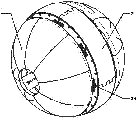
[0030] see Figure 1 ~ Figure 4 , this fast steering spherical robot comprises 8 pairs of spherical surface ball feet (1) on both sides, 8 pairs of ball foot linkages (4), two ball foot drive mechanisms (21), a central spherical wheel frame (23) and A central pendulum mechanism (22) is characterized in that: the 8 pairs of spherical ball feet (1) are respectively movably connected to two ball foot drive mechanisms (21) through 8 pairs of ball foot linkage mechanisms (4), and the two The football foot driving mechanism (21) is respectively installed on the two side walls of the central spherical wheel frame (23); the central pendulum mechanism (22) is fixedly installed in the central spherical wheel frame (23); There is a brushless motor (13) in the pendulum mechanism (22) to drive the central pendulum mechanism to change its center of gravity, and to control the robot to move back and forth in the normal direction of the central axis; each of the two ball foot drive mechanisms...

Embodiment 2

[0032] This embodiment is basically the same as Embodiment 1, and the special features are as follows:

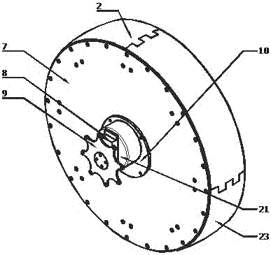
[0033] The central spherical wheel frame body (23) is composed of polylactic acid spherical wheel frame (2) with elastic spherical wheel frame (2) fixedly connected with carbon fiber circular plates (7) on both sides, polylactic acid spherical wheel frame (2) ) is divided into 4 parts to reduce the volume of 3D printing, the polylactic acid spherical wheel frame (2) is connected by studs, and the carbon fiber circular plate (7) and polylactic acid spherical wheel frame (2) are connected by bolts connected.

[0034] The ball foot driving mechanism (21) includes a steering gear (8), a carbon fiber steering wheel (9) and a steering gear frame (10), and the steering gear (8) passes through the steering gear frame (10) Fixedly install the carbon fiber circular plate (7) on the side of the central spherical wheel frame body (23), and the output shaft of the steering gear (8) is ...

Embodiment 3

[0039] see Figure 1 ~ Figure 4 , This fast steering spherical robot includes 8 pairs of ball feet (1) deployment mechanisms on both sides and a pendulum-type drive structure in the center.

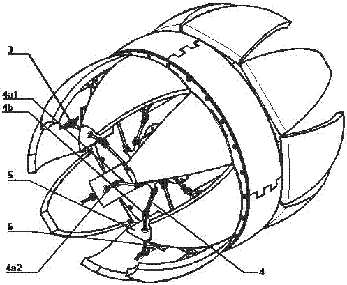
[0040] 1) The football foot (1) deployment mechanism: it is composed of a football foot (1) made of polylactic acid, two pairs of carbon fiber rods (4a) and three sets of spherical hinges. The slide slots (3) on the football foot ) is connected to the carbon fiber rods (4a1, 4a2), and the rigidity is strengthened through the fixing plate (5), and the ball foot (1) is connected to the carbon fiber circular plate (7) through the nylon hinge (6);

[0041] 2) The carbon fiber steering wheel (9) is connected with the carbon fiber rods (4a1, 4a2) through hinges (4b). The hinges (4b) are connected, and the carbon fiber rudder plates (9) of different structures determine the motion planning in different situations.

[0042] 3) The steering gear (8) is fixed on both sides of the carbon fiber cir...


PUM


Abstract

The invention discloses a fast steering spherical robot. It includes a total of 8 pairs of spherical ball feet on both sides, 8 pairs of ball foot linkage mechanisms, two ball foot drive mechanisms, a central spherical wheel frame and a central pendulum mechanism. It is characterized in that: the 8 pairs of spherical ball feet The two ball foot drive mechanisms are respectively connected through 8 pairs of ball foot linkage mechanisms. The two ball foot drive mechanisms are respectively installed on the two side walls of the central spherical wheel frame; the central pendulum mechanism is fixedly installed on the Inside the central spherical wheel frame; there is a brushless motor in the central pendulum mechanism to drive the central pendulum mechanism to change its center of gravity, and to control the robot to move forward and backward in the normal direction of the central axis; The steering gear drives the opening and closing angles of 8 pairs of spherical ball feet through 8 pairs of ball foot linkages respectively, so as to change the left and right inclination angles on the central axis of the robot. The invention can turn smoothly under high-speed driving, has good flexibility, and its structure has universal applicability.

Description

technical field [0001] The invention relates to the field of spherical robots, in particular to a fast-turning spherical robot. Background technique [0002] As a fully enclosed robot, the spherical robot has extremely special advantages in scientific exploration. In order to explore some special harsh environments, such as sand dunes, snow, ice crevasses, etc., traditional wheeled or legged robots will face various problems. Spherical robots have gained attention due to their ability to adapt to the field. But also at present most of the internally driven spherical robots will decelerate when turning, so as to ensure that the robot does not lose control when turning, and some even turn to can only be completed after stopping. In nature, such as the armadillo or the ball millipede, although they have a spherical shape, the main form of locomotion is non-spherical. So how to break through the concept of the constant spherical state of the spherical robot, so as to achieve ...

Claims


Application Information

Patent Timeline
Patent Type & Authority Patents(China)
IPC IPC(8): B62D57/02
Inventor 罗均姚骏峰邹旭东祝川谢少荣冯凯
Owner SHANGHAI UNIV
Why Eureka
Try Eureka