
Fuel cutoff valve

a technology of fuel cutoff valve and valve body, which is applied in the direction of functional valve types, operating means/release devices of valves, machines/engines, etc., can solve the problem that the fuel cutoff valve cannot be quickly closed to prevent and achieve excellent valve re-opening properties, effectively preventing the leakage of fuel

Inactive Publication Date: 2006-01-03
TOYODA GOSEI CO LTD
View PDF4 Cites 21 Cited by
  • Summary
  • Abstract
  • Description
  • Claims
  • Application Information

AI Technical Summary

Benefits of technology

[0007]The object of the present invention is thus to provide a fuel cutoff valve that quickly closes and effectively prevents leakage of fuel from a fuel tank even under a large transverse force, for example, at the time of a turn of a vehicle, or under a large upthrust force.
[0011]While the liquid level in the fuel tank is lower than the preset first liquid level in the course of fuel supply, the fuel cutoff valve of the invention connects with outside (a canister) to release the fuel vapor out of the fuel tank. When the liquid level in the fuel tank exceeds the preset first liquid level, the first float moves up and closes the first connection conduit. The inner pressure of the fuel tank then temporarily rises to prompt an auto stop of a fuel feed gun. This arrangement effectively prevents leakage of the fuel from the fuel tank to the outside.
[0014]The second float has the greater specific gravity than that of the fuel. The second float is thus immediately separated from the first float when the liquid level becomes lower the preset second liquid level. This quickly cancels the pressure difference between the inside and the outside of the fuel tank. This arrangement effectively prevents the lightweight first float from adhering to the seat of the first connection conduit and ensures the excellent valve re-opening properties.
[0015]In the vehicle rolling attitude and the vehicle turnover attitude, the second float having the large specific gravity presses against and sinks the first float to block both the first connection conduit and the second connection conduit. This arrangement effectively prevents leakage of the fuel from the fuel tank.

Problems solved by technology

Namely the prior art fuel cutoff valve can not quickly close to prevent leakage of the fuel from the fuel tank under a large transverse force or under a large upthrust force, which may arise during a turn of the vehicle.

Method used


Image

  • Fuel cutoff valve
  • Fuel cutoff valve
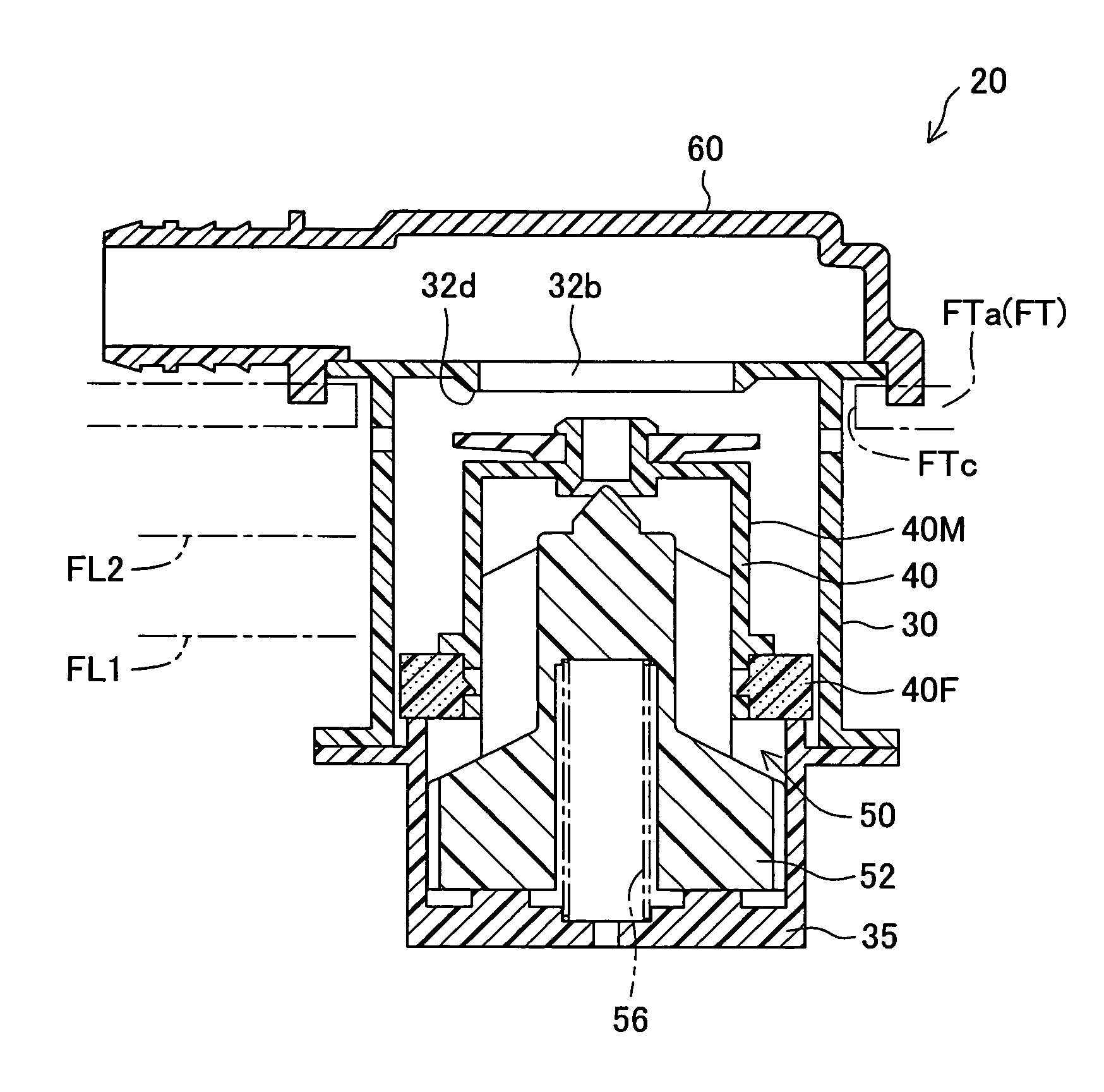
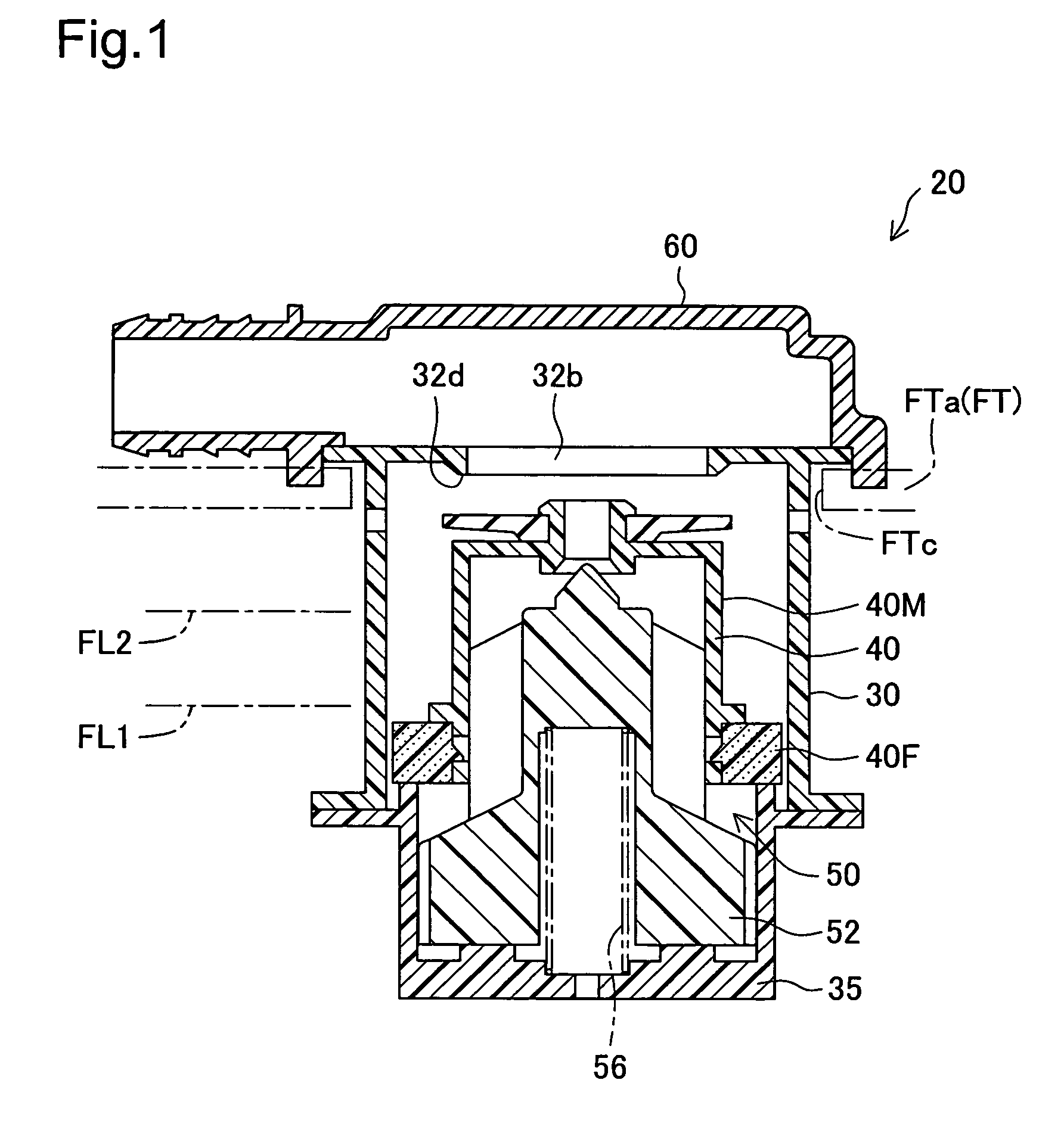
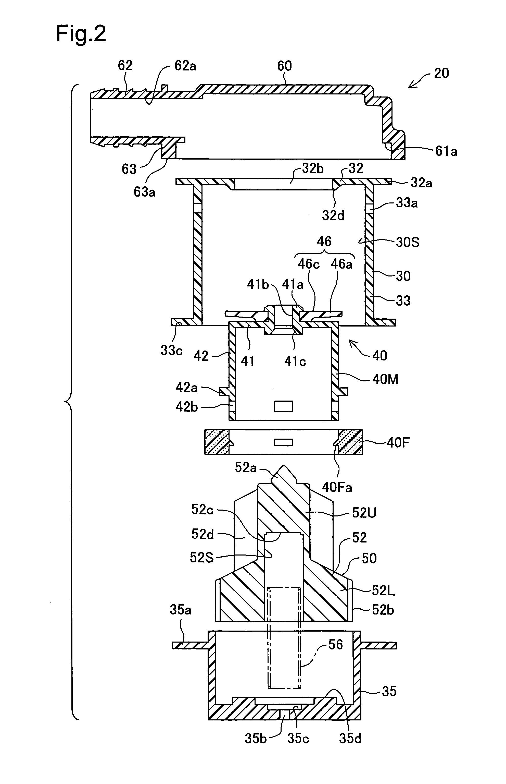
  • Fuel cutoff valve

Examples


Embodiment Construction

[0027](1) General Structure of Fuel Cutoff Valve 20

[0028]FIG. 1 is a sectional view showing a fuel cutoff valve 20 attached to an upper wall of a fuel tank FT of a vehicle in one embodiment of the invention. The surface of the fuel tank FT is made of a composite resin material containing polyethylene. An attachment hole FTc is formed in a tank upper wall FTa of the fuel tank FT. The lower portion of the fuel cutoff valve 20 is inserted into the attachment hole FTc, so that the fuel cutoff valve 20 is fixed to the tank upper wall FTa.

[0029]The fuel cutoff valve 20 works to prevent an outflow of fuel to outside (a canister), when the liquid level in the fuel tank FT rises to a preset liquid level, for example, in the course of fuel feed. There are two preset liquid levels, a first liquid level FL1 that represents a full level of fuel supply and a second liquid level FL2 that is higher than the first liquid level FL1 and is set to prevent leakage of fuel in a tilted attitude of the veh...


PUM


Abstract

A fuel cutoff valve has a casing main body, a first float having a smaller specific gravity than a fuel, a second float having a greater specific gravity than the fuel, and a spring. The first float has a float main body and a buoyancy body of a foamed resin. The first float's specific gravity therefore is smaller than the fuel's specific gravity. The first float rises by buoyancy to close a first connection conduit, when a liquid level in a fuel tank exceeds a first liquid level. The second float rises by buoyancy and pressing of the spring to close a second connection conduit, when the liquid level exceeds a second liquid level, higher than the first liquid level. The second float lowers to open the second connection conduit, when the liquid level becomes lower than the second liquid level but is still higher than the first liquid level.

Description

[0001]This application claims the benefit of priority from Japanese Application No. 2003-82931 filed Mar. 25, 2003, the content of which is incorporated herein by reference.BACKGROUND OF THE INVENTION[0002]1. Field of the Invention[0003]The present invention relates to a fuel cutoff valve that is attached to a top end of a fuel tank and functions to connect and disconnect the fuel tank with and from outside according to the liquid level in the fuel tank.[0004]2. Description of the Related Art[0005]A known fuel cutoff valve is disclosed, for example, in JP No. 6-297968A. This prior art fuel cutoff valve has a casing with a connection conduit connected to outside of a fuel tank, a cylindrical first float valve arranged in a valve chamber in the casing, a second float valve arranged in a vertically movable manner in a storage chamber of the first float valve, and a spring supporting these elements. The first float valve closes the connection conduit when a liquid level in the fuel tank...

Claims


Application Information

Patent Timeline
Patent Type & Authority Patents(United States)
IPC IPC(8): F16K24/04B60K15/01F02M37/00F16K24/00F16K31/28
CPCF16K24/042Y10T137/3099Y10T137/0874
Inventor NISHI, HIROSHI
Owner TOYODA GOSEI CO LTD
Learn More