

Shaped and fabricated formwork construction process used for shear wall at expansion and contraction joint
A technology of combined formwork and construction technology, which is applied in the direction of formwork/formwork/work frame, connectors of formwork/formwork/work frame, and preparation of building components on site, which can solve the problems affecting project quality, construction period, expansion and contraction, etc. Shorten the construction period, reduce the construction difficulty and operation risk, and ensure the construction quality and safety.
- Summary
- Abstract
- Description
- Claims
- Application Information
AI Technical Summary
Problems solved by technology
Method used
Image

Examples
Embodiment Construction
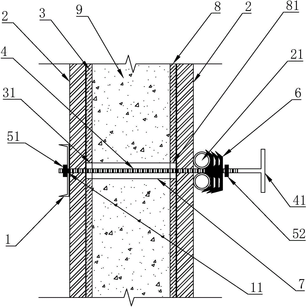
[0025] refer to Figure 1 to Figure 2 Further description will be made on the embodiment of the stereotyped composite formwork and its construction technology of the present invention.
[0026] A construction process for a stereotyped composite formwork for a shear wall at an expansion joint, including channel steel 1, steel pipe 2, plank, steel bar, release agent, double-sided adhesive, wall-penetrating screw 4, pull nut 51, fastening Nut 52, fastener 6, PVC casing 7, comprise following construction steps:
[0027] 1) Make a stereotyped combination template:
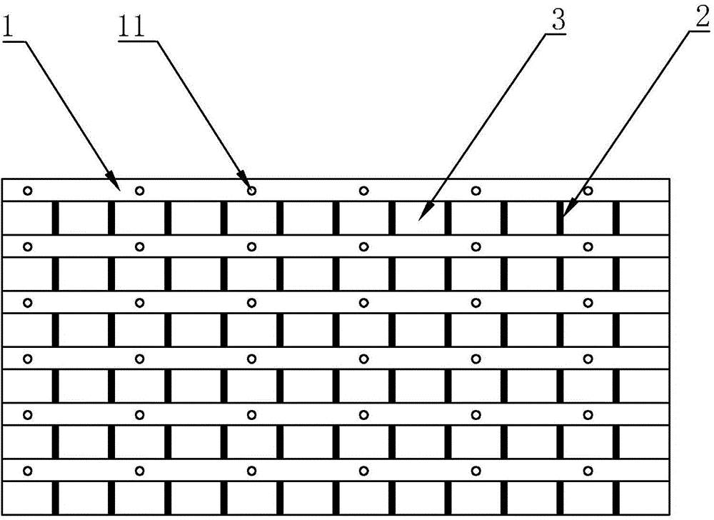
[0028] a. According to the size of the wall body 9 at the expansion joint, use wooden planks to form a formwork 3 of corresponding size, and initially fix the planks with nails; the planks are 18mm thick clad wood plywood commonly used on the construction site, and the joints are planed with a woodworking saw , to ensure that the patchwork is dense;
[0029] b. Arrange a number of steel pipes 2 in parallel on the spl...
PUM
 Abstract
Description
Claims
Application Information