Structure and Method of Groove Loss Reduction for End Wall of New Turbine Cascade

Active Publication Date: 2015-12-30
SHANGHAI JIAO TONG UNIV
View PDF4 Cites 1 Cited by
  • Summary
  • Abstract
  • Description
  • Claims
  • Application Information

AI Technical Summary

Problems solved by technology

[0009] Aiming at the defects in the prior art, the purpose of the present invention is to provide a new structure for reducing the secondary flow loss, so as to solve the problem of secondary flow and secondary flow caused by the transverse pressure gradient in the cascade channel in the existing application. Loss of technical problems, so as to achieve the purpose of improving the overall performance of the turbine

Method used


Image

  • Structure and Method of Groove Loss Reduction for End Wall of New Turbine Cascade
  • Structure and Method of Groove Loss Reduction for End Wall of New Turbine Cascade
  • Structure and Method of Groove Loss Reduction for End Wall of New Turbine Cascade

Examples


Embodiment Construction

[0043] The present invention will be described in detail below in conjunction with specific embodiments. The following examples will help those skilled in the art to further understand the present invention, but do not limit the present invention in any form. It should be noted that those skilled in the art can make several modifications and improvements without departing from the concept of the present invention. These all belong to the protection scope of the present invention.

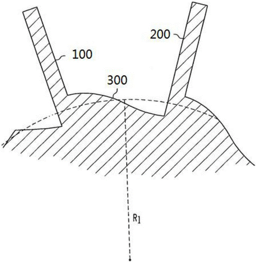
[0044] The invention relates to a novel groove loss structure of the end wall of the turbine blade cascade. The structure is arranged on the end wall of the turbine blade cascade to reduce secondary flow loss. Wherein, the end wall of the turbine cascade is located on the hub side of the plurality of turbine blades arranged in a ring;

[0045] The groove reduction structure of the novel turbine blade cascade end wall is arranged on the turbine blade cascade end wall and connected with the turbine ...


PUM


Abstract

The invention provides a groove impairment structure of a novel turbine blade grid end wall. The structure is arranged on the turbine blade grid end wall, and is used for reducing secondary flow losses. The turbine blade grid end wall is located on the hub side of a plurality of turbine blades arranged in an annular mode. The invention further provides a corresponding method. The groove impairment structure of the novel turbine blade grid end wall is arranged on the turbine blade grid end wall, and is connected with the turbine blade grid end wall through a laser machining method. Transverse motion of end fluid can be obstructed, transverse pressure gradient can be reduced, and therefore the strength of a horseshoe vortex pressure side branch and a channel vortex is reduced, and the aim of reducing the secondary flow losses is achieved.

Description

technical field [0001] The present invention relates to gas turbine engines, and in particular, to a novel turbine cascade end wall grooved relief structure and method. Background technique [0002] A gas turbine engine is mainly composed of an inlet, a compressor, a combustion chamber, a turbine, and a nozzle. After the air enters the gas turbine from the intake port, it is first pressurized into high-pressure gas by the compressor, and then the fuel injected by the fuel injector is mixed with air and burnt into high-temperature and high-pressure gas in the combustion chamber, and then enters the turbine section to drive the turbine, and the gas kinetic energy converted into mechanical energy output. [0003] Among them, the turbine is a rotary power machine that converts the kinetic energy of the flowing working medium into mechanical work, and it is one of the main components of the gas turbine engine. When the gas flows through the turbine cascade channel, there is a p...

Claims


Application Information

Patent Timeline
Patent Type & Authority Patents(China)
IPC IPC(8): F01D5/14F01D9/02
Inventor 张强苗昕齐欢
Owner SHANGHAI JIAO TONG UNIV
Why Eureka
Try Eureka