Combined oil-control ring

A technology of oil control ring and expansion ring, which is applied to piston rings, machines/engines, mechanical equipment, etc., can solve problems such as consumption, and achieve the effect of realizing oil consumption, small tension deviation, excellent wear resistance and sludge resistance

Active Publication Date: 2014-08-27
RIKEN CO LTD
View PDF9 Cites 12 Cited by
  • Summary
  • Abstract
  • Description
  • Claims
  • Application Information

AI Technical Summary

Problems solved by technology

[0005] However, if the reduction of tension is pursued, the problem of oil consumption must be faced, so the improvement of the combined oil ring accompanying the reduction of oil consumption can also be said to be an eternal problem.

Method used


Image

  • Combined oil-control ring
  • Combined oil-control ring
  • Combined oil-control ring

Examples


Embodiment 1

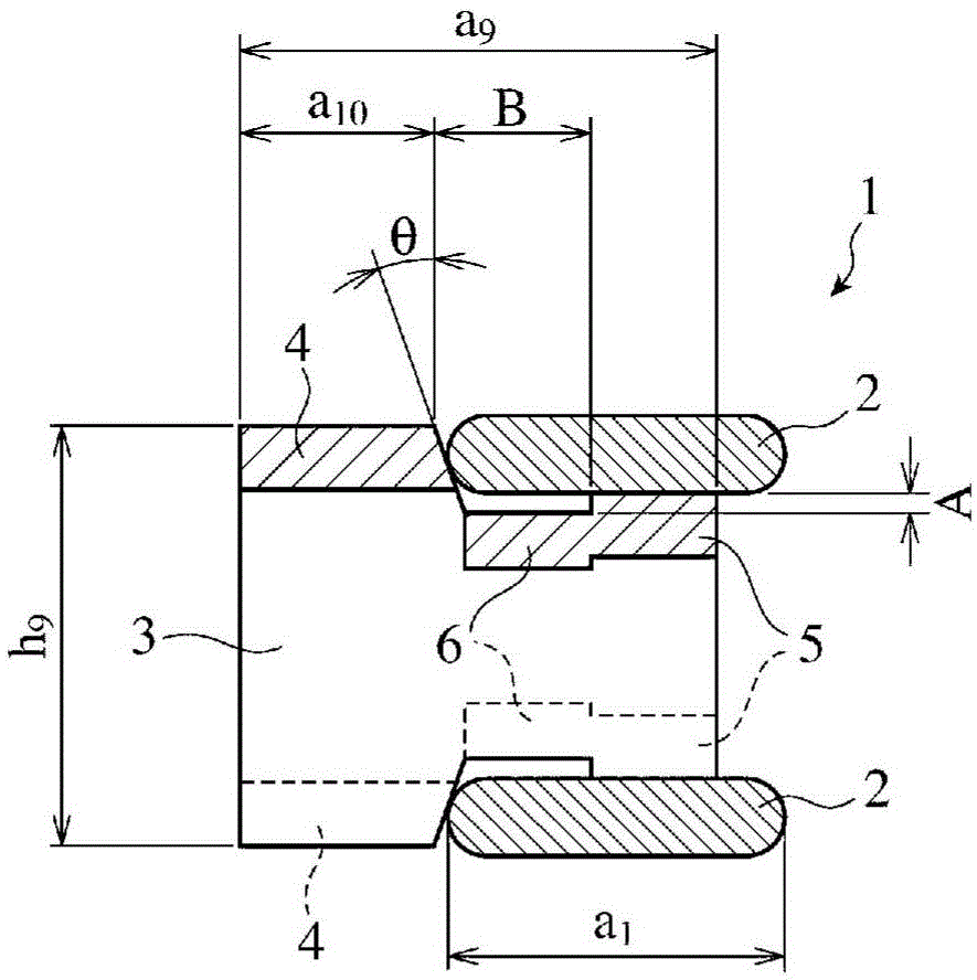
[0037] The spacer expansion ring is formed from a 2.50mm×0.25mm rolled strip (SUS304 material) using a gear forming method, and the side rail is formed from a 1.60mm×0.40mm rolled strip (SUS440B) by a coiling method. The following dimensions. The size of the combined oil ring produced is:

[0038] Nominal diameter: 82.5mm

[0039] Expanding ring width h 9 : 2.43mm

[0040] Height of external expansion ring a 9 : 2.5mm

[0041] ear height a 10 : 1.2mm

[0042] Support width A: 0.12mm

[0043] Middle part height B: 0.8mm

[0044] Side rail thickness a 1 : 1.6mm. In addition, the tension value is 23N as the target value to adjust the expanded length of the spacer expansion ring.

Embodiment 2~5 and comparative example 2

[0057] Using the same rolled strips for spacer expansion rings and rolled strips for side rails as in Example 1, a formed gear having the dimensions shown in Table 1 was prepared, and a combination oil ring was produced so that the tension value was 22N. . For these combined oil rings, an engine test was conducted under the same conditions as in Example 1, and the amount of oil consumption was measured. The above results are shown in Table 1 together with the results of Example 1 and Comparative Example 1.

[0058] 【Table 1】

[0059]

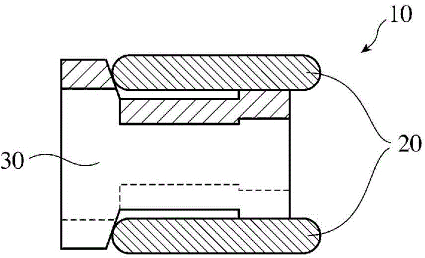
[0060] Here, the width A in the axial direction of the supporting portion was 0.12 mm in all except for Comparative Example 1 which was 0.05 mm.

[0061] The above results show that the thinner (shorter) the thickness of the side rail, or the thicker (longer) the ear height of the spacer expansion ring is, that is, a 1 / a 9 smaller, or a 10 / a 9 The larger the value, the less oil consumption. It is considered that reducing the thicknes...

Embodiment 6~8、 comparative example 3

[0064] In Examples 6 to 8 and Comparative Example 3, combined oil rings with the same size and shape as those of Examples 1, 4, 5 and Comparative Example 2 were used respectively. Using the same engine as the engine, the durability test was carried out, and the oil ring groove wear of the piston was measured. Durability test The combination oil rings of Examples 6-8 and Comparative Example 3 were respectively attached to four cylinders, and the test conditions were 6500 rpm and full load (WOT: Wide Open Throttle) conditions. Of course, the rings used for the above-mentioned engine are used for the first and second rings. The amount of groove wear of the oil ring groove was evaluated based on the amount of increase in the axial width of the end portion of the oil ring groove of the piston of each cylinder before and after the test for a predetermined time. The results are shown in Table 2.

[0065] 【Table 2】

[0066]

[0067] [3] Determination of sludge accumulat...


PUM


Abstract

Provided is a combined oil-control ring which has excellent oil consumption characteristics, abrasive resistance and sludge resistance. The combined oil-control ring comprises a pair of circular ring shaped side rails with openings; and a wave-shaped separating outer tensioner ring clamped between the pair of circular ring shaped side rails and possessing ear parts for pressing inner peripheral surfaces of side rails in the inner periphery, wherein the thickness (a1) of the side riails is set to be 50-90% of a outer tensioner ring height (a9) of the separating outer tensioner ring, or the ear height (a10) of the ear of the separating outer tensioner ring is set to be 23-60% of the outer tensioner ring height (a9).

Description

technical field [0001] The invention relates to a combined oil control ring (hereinafter also referred to as "combined oil ring"), which is installed on the piston of the engine for oil control and includes a pair of annular side rails and a spaced outer expansion ring, especially relates to improving Combined oil control ring with excellent follow-up performance and reduced oil consumption. Background technique [0002] In recent years, from the viewpoint of preventing global warming, reduction of CO 2 In automotive engines, the goal is to improve fuel economy, improve combustion efficiency, and especially improve fuel economy, and is improving the friction of the sliding part of the piston system. It is especially important to reduce the tension of the piston rings. Among them, the tension of the oil control ring accounts for more than 50% of the total tension of the piston rings. Therefore, measures to reduce the tension are being studied. However, lowering the tension ...

Claims


Application Information

Patent Timeline
Patent Type & Authority Applications(China)
IPC IPC(8): F02F5/00
CPCF16J9/068F16J9/065
Inventor 薮根博幸藤田正显杉原弘幸
Owner RIKEN CO LTD
Why Eureka
Try Eureka