Beam-type burner

A burner, beam technology, applied in burners, gas fuel burners, combustion methods, etc., can solve problems such as inconvenience

Inactive Publication Date: 2014-08-27
LUOYANG YUXIN ENG TECH
View PDF6 Cites 2 Cited by
  • Summary
  • Abstract
  • Description
  • Claims
  • Application Information

AI Technical Summary

Problems solved by technology

[0003] This shows that above-mentioned existing burner obviously still has inconvenience and defect in structure and use, and urgently needs to be further improved

Method used


Image

  • Beam-type burner
  • Beam-type burner
  • Beam-type burner

Examples


Embodiment Construction

[0027] In order to further explain the technical means and effects of the present invention to achieve the intended purpose of the invention, the specific implementation, structure, characteristics and effects of the beam burner proposed according to the present invention will be described below in conjunction with the accompanying drawings and preferred embodiments. , as detailed below.

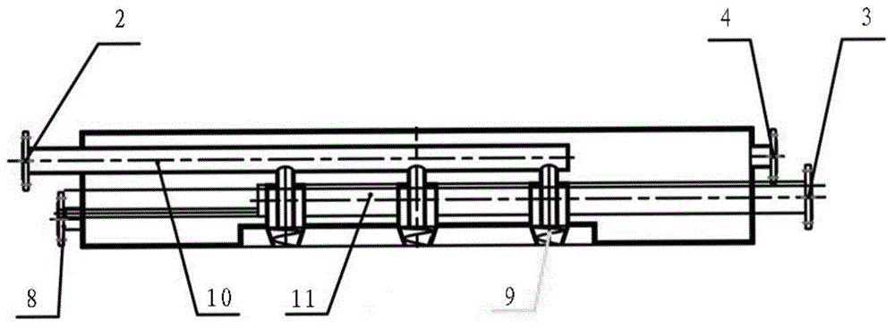
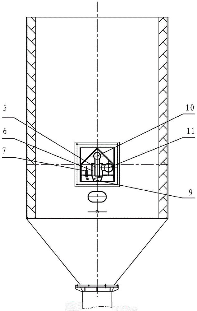
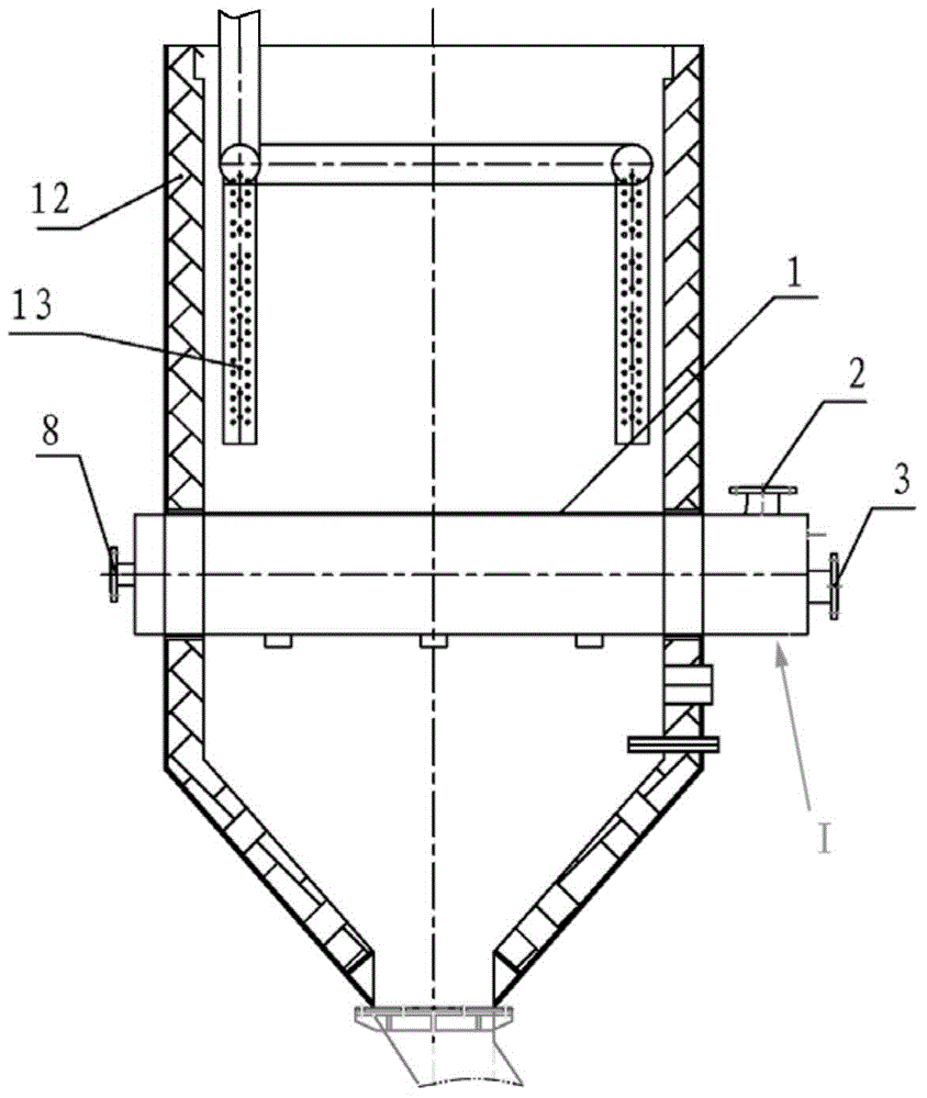
[0028] see figure 1 , figure 2 , image 3 as shown, figure 1 It is a structural schematic diagram of the beam burner of the present invention. figure 2 It is a schematic diagram of the installation structure of the beam burner of the present invention. image 3 for figure 2 side view.

[0029] The present invention provides a beam type burner, including an alloy furnace 12, a furnace body smoke exhaust device 13, and a beam type burner I, wherein the furnace body smoke exhaust device 13 is arranged inside the alloy furnace 12; wherein the beam type burner I It is directly installed...


PUM


Abstract

The invention relates to a beam-type burner. A gas pipe, an air pipe and an ever-burning fire tube are arranged in a square beam, the air pipe is located on the outer side of the gas pipe, a gas and air mixing structure is formed between the inner wall of the air pipe and an air branch port and a gas branch port, and the ever-burning fire tube is arranged on the outer side of a whirlwind flaming port. Cooling media enters the burner from the inlet of a cooling pipe and flows out from the outlet of the cooling pipe after passing a cooling cavity. The bottom of the beam is connected with a short tube to from the whirlwind flaming port, and the front end of the air branch port extends out of the beam. The gas branch port is located in the air branch port to form the single burner. The burner is of a beam-type structure and can be directly arranged on the lower portion of the inside of an alloy furnace, the occupied space is small, and burning efficiency is improved. The beam-type burner has the advantages of enabling alloy materials to be evenly heated, meeting the requirements of the alloy heating process, being high in burning efficiency, small in occupied space, high in adaptability and long in service life, fully using energy resources and saving energy, and flames do not need to be adjusted.

Description

technical field [0001] The invention relates to a burner, in particular to a beam type burner for baking metallurgical ferroalloy materials. Background technique [0002] At present, the burners used in the baking of alloy furnaces in iron and steel plants are mainly composed of gas pipes and air pipes, and are installed on the side of the alloy furnace body. The burners of this structure need to add additional space inside the alloy furnace to form The combustion chamber has a lot of holes in the middle, and the hot gas is sprayed from the holes to the alloy charge, so as to achieve the purpose of indirect heating. Because the grid is often subjected to heat and cold, it is prone to deformation and damage, and needs to be replaced after a period of use. The disadvantage of this type of combustion chamber is that the combustion space is small, the fuel cannot be completely burned in this combustion space, and the heat generated during combustion cannot fully and evenly heat...

Claims


Application Information

Patent Timeline
IPC IPC(8): F23D14/24F23C5/00
Inventor 安跃锋赵项林李辽宁叶锐
Owner LUOYANG YUXIN ENG TECH
Why Eureka
Try Eureka