
A tank clearing device

A kind of equipment and tank clearing technology, which is applied in the field of tank clearing equipment for shell and tube heater fouling cleaning in sugarcane sugar factories. It can solve the problems of complex structure and few types, so that it is not easy to entangle, reduce the time of assembly and disassembly, and improve the support way effect

Active Publication Date: 2016-06-15
GUANGXI YEMAO ELECTROMECHANICAL AUTOMATION
View PDF6 Cites 0 Cited by
  • Summary
  • Abstract
  • Description
  • Claims
  • Application Information

AI Technical Summary

Problems solved by technology

[0005] In the prior art, tank clearing equipment has problems such as few types and complicated structure. The technical problem to be solved by the present invention is: aiming at the technical problems existing in the prior art, a tank clearing equipment with two-stage rotating arms is invented

Method used


Image

  • A tank clearing device
  • A tank clearing device
  • A tank clearing device

Examples


Embodiment Construction

[0037] The present invention will be further described in detail below in conjunction with the accompanying drawings and specific embodiments.

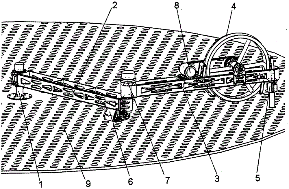
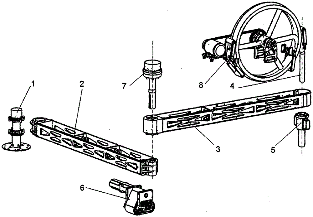
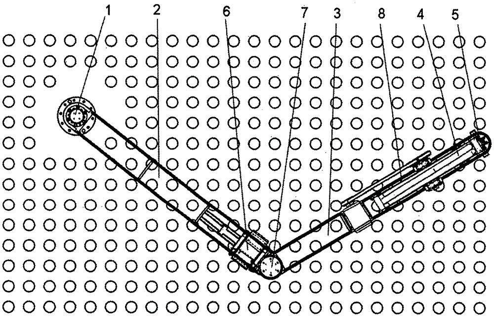
[0038] Such as Figure 1-4 As shown, a tank clearing equipment includes a central support 1, a water pipe 4, a water pipe feeding device 8, and an end clamping device 5, and is characterized in that it also includes a primary rotary arm 2, a secondary rotary arm 3, a support drive Device 6, driving device 7; one end of the primary pivoting arm 2 is hinged with the center support 1, and the other end is hinged with the secondary pivoting arm 3; the supporting drive device 6 is fixed at the end of the primary pivoting arm 2 for Used to support the first boom 2 and drive the first boom 2 to rotate; the driving device 7 is arranged on the hinge shaft of the primary boom 2 and the secondary boom 3, and is used to drive the secondary boom 3 to rotate; A water pipe feeding device 8 is fixed on the secondary rotating arm 3 , and an end clamp...


PUM


Abstract

The invention discloses a tank clearing device, which includes a central support, a water pipe, a water pipe feeding device, and an end clamping device, and is characterized in that it also includes a first-stage rotating arm, a second-stage rotating arm, a supporting drive device, and a driving device; One end of the primary boom is hinged to the central support, and the other end is hinged to the secondary boom; the supporting drive device is fixed at the end of the primary boom for supporting and driving the first boom Rotation; the driving device is arranged on the hinge shaft of the primary and secondary rotary arms, and is used to drive the secondary rotary arm to rotate; the secondary rotary arm is fixed with a water pipe feeding device and a terminal locking device It is fixed at the end of the secondary rotating arm, and the water pipe runs through the end clamping device. The invention utilizes the layout characteristics of the two-stage pivoting arms, adopts a modular design, has a simple structure, and is convenient to assemble and disassemble.

Description

technical field [0001] The invention relates to a tank cleaning device, in particular to a tank cleaning device used for cleaning fouling of a tubular heater in a sugarcane sugar factory. Background technique [0002] The heaters in sugarcane sugar factories are mainly shell and tube heaters. Due to the influence of the sugar factory's sugar production process, after a period of use, the shell and tube heaters will deposit sulfurous acid with uneven thickness on the inner wall of the tubes. Calcium (scaling). After fouling, the heat transfer efficiency of the heater is greatly reduced. If it is not cleaned up in time, it will directly affect the normal progress of the sugar making process. Therefore, in order to remove the fouling, every sugar factory must invest a lot of manpower and material resources. [0003] At present, the cleaning methods for the tubular heaters in my country's sugarcane sugar factories mainly include high-pressure water jet cleaning, and rely entir...

Claims


Application Information

Patent Timeline
Patent Type & Authority Patents(China)
IPC IPC(8): F28G9/00F28G15/04F28G15/00
Inventor 潘存云徐海军叶丽娜曹正虎
Owner GUANGXI YEMAO ELECTROMECHANICAL AUTOMATION
Learn More