
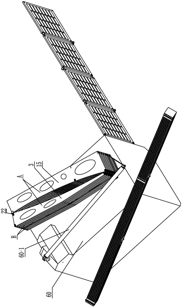
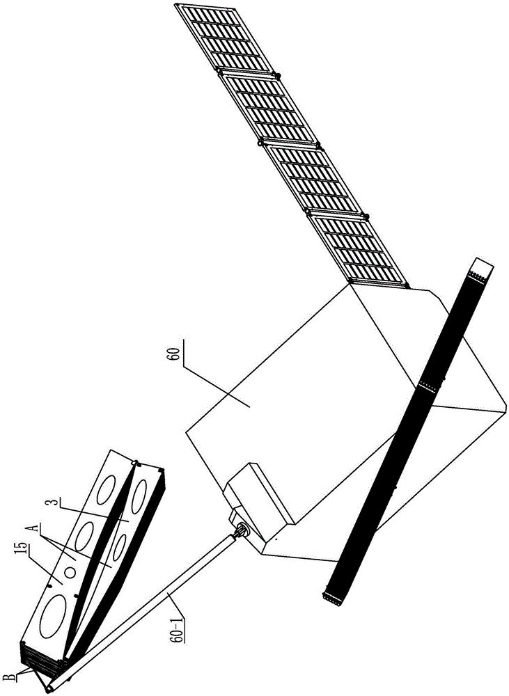
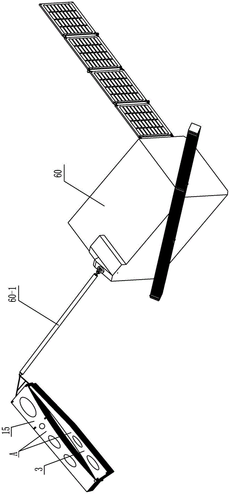
A Modular Spatial Parabolic Cylindrical Foldable Antenna Mechanism

A parabolic cylinder and modular technology, which is applied in the direction of antenna support/installation device, etc., can solve the problems of umbrella antenna structure with poor overall stiffness, inability to form a parabolic cylinder, and low surface accuracy, so as to reduce the launch cost, Save payload space and increase stiffness when folded

Active Publication Date: 2016-08-24
HARBIN INST OF TECH
View PDF4 Cites 3 Cited by
  • Summary
  • Abstract
  • Description
  • Claims
  • Application Information

AI Technical Summary

Problems solved by technology

[0005] The present invention aims to solve the problem of low surface precision, poor stability, poor overall rigidity, umbrella-shaped antenna structure that is not suitable for reflective surface stretching and forming in the existing unfolded parabolic cylindrical antenna structure, and the deployable truss antenna The structure can only be unfolded in one direction and cannot form a parabolic cylinder, so a modular space parabolic cylinder folding antenna mechanism is provided

Method used


Image

  • A Modular Spatial Parabolic Cylindrical Foldable Antenna Mechanism
  • A Modular Spatial Parabolic Cylindrical Foldable Antenna Mechanism
  • A Modular Spatial Parabolic Cylindrical Foldable Antenna Mechanism

Examples


specific Embodiment approach 1

[0026] Specific implementation mode one: combine Figure 1-Figure 25 Explain that a modular space parabolic cylinder folding antenna mechanism in this embodiment includes two synchronous folding module racks A, multiple positioning folding module racks B, several folding arms C and several tensioning ropes 48;

[0027] Each folding arm C includes an elastic hinge C1, two folding arm bars 26 and two external connection joints 25, one end of the two folding arm bars 26 is connected by an elastic hinge C1, and the other end of the two folding arm bars 26 Each end is equipped with an external connection joint 25;

[0028] Each positioning and folding module frame B includes an outer support plate 3 and an inner support plate 15, and the installation end 3-1 of the outer support plate 3 is rotationally connected with the installation end 15-1 of the inner support plate 15;

[0029] Each synchronous folding module rack A includes an outer support plate 3, an inner support plate 15...

specific Embodiment approach 2

[0040] Specific implementation mode two: combination Figure 5 To illustrate, the tension pull cord 48 in this embodiment is a Kevlar drawstring or a carbon fiber rope. In this way, the Kevlar rope is light in weight, high in strength, stable in size and high in mechanical strength; the conductivity of the carbon fiber rope is stable, meeting actual needs. Others are the same as in the first embodiment.

specific Embodiment approach 3

[0041] Specific implementation mode three: combination Figure 13 and Figure 14 To illustrate, the folding boom 26 in this embodiment is made of carbon fiber winding. With such setting, the strength is high, the weight is light, and the fatigue resistance is good, which meets the design requirements and actual needs. Others are the same as in the first or second embodiment.


PUM


Abstract

The invention provides a modularized space parabolic cylinder antenna folding and unfolding mechanism and relates to an antenna mechanism in order to solve the problems that an existing unfolded type parabolic cylinder antenna structure is low in molded surface accuracy, poor in stability and low in integral rigidity, an umbrella antenna structure is not suitable for the structure formed by stretching a reflecting surface, an unfolding truss antenna structure can only be unfolded unidirectionally, and a parabolic cylinder can not be formed. The modularized space parabolic cylinder antenna folding and unfolding mechanism comprises two synchronous folding and unfolding module supports, multiple locating folding and unfolding module supports, a plurality of folding and unfolding arms and a plurality of tensioning pull cords. Each folding and unfolding arm comprises an elastic hinge, two folding and unfolding arm levers and two outer connectors. Each synchronous folding and unfolding module support comprises an outer supporting plate, an inner supporting plate, locking and limiting devices and a rotary connecting device. Synchronous folding and unfolding modules are arranged on the two sides of the multiple locating folding and unfolding module supports respectively. The mounting end of the outer supporting plate of each synchronous folding and unfolding module support and the mounting end of the inner supporting plate of the synchronous folding and unfolding module support are rotatably connected through the corresponding rotary connecting device. The modularized space parabolic cylinder antenna folding and unfolding mechanism is applied to satellites or space stations.

Description

technical field [0001] The invention relates to an antenna mechanism, in particular to a modular expandable antenna mechanism composed of a plurality of modules for expanding and supporting a satellite-borne parabolic cylindrical reflector antenna, and belongs to the technical field of satellite antenna structures. Background technique [0002] With the development of technology and the promotion of applications, in the fields of satellite communication, wireless broadcasting system, earth observation, land remote sensing, deep space exploration and deep space communication, space-borne large-scale deployable antennas have been widely used in navigation satellites, communication satellites, etc. , relay satellites, meteorological satellites and reconnaissance satellites. In order to meet the needs of multi-function, multi-band, large capacity, high power, and long life, satellite antennas are required to have large diameter, high precision, light weight, and high rigidity. H...

Claims


Application Information

Patent Timeline
Patent Type & Authority Patents(China)
IPC IPC(8): H01Q1/12
Inventor 郭宏伟刘荣强邓宗全史创
Owner HARBIN INST OF TECH
Learn More