Supercharge Your Innovation With Domain-Expert AI Agents!

Method and projection device to mark a surface

A technology of marking and equipment, which is applied in the direction of instruments, applications, and optical devices used in radiological diagnosis, can solve problems such as measurement errors, and the risk of tape measure slipping that becomes difficult to operate, and achieves the effect of broadening the scope of application

Inactive Publication Date: 2014-09-03
SIEMENS AG
View PDF7 Cites 1 Cited by
  • Summary
  • Abstract
  • Description
  • Claims
  • Application Information

AI Technical Summary

Problems solved by technology

The use of a tape measure, for example in surgical interventions on a patient, has a number of disadvantages for the operator and / or the patient
Among these are, for example, increased costs for ensuring the sterility of the measuring tape, handling which becomes more difficult on some body parts, risk of the measuring tape slipping and other unique handling drawbacks which can lead to measurement errors

Method used


Image

  • Method and projection device to mark a surface
  • Method and projection device to mark a surface
  • Method and projection device to mark a surface

Examples


Embodiment Construction

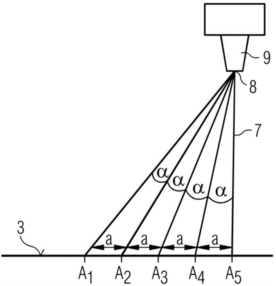
[0041] figure 1 A laser system 9 with a deflection unit 8 and a planar surface 3 are shown as radiation means, which are directed towards each other. The laser system 9 emits a fan-shaped beam 7 towards the surface 3 . Any beam 7 and each closest beam 7 are always in the same differential radiation angle α relative to each other. The nature of the plane of the surface 3 and the same differential radiation angle α of adjacent beams 7 cause: The beam 7 hits the point A on the surface 3 1 ,A 2 ,A 3 ,A 4 ,A 5 , where each point A 1 ,A 2 ,A 3 ,A 4 ,A 5 are all at the same distance a with respect to the neighboring points. This also means that at point A 1 with point A 2 The path between a and the point A at 2 and point A 3 between or point A 3 and point A 4 between or point A 4 and point A 5 The path a between them is the same length. With the aid of this method, exact, uniform raster measurements or measurement grids 5 can be produced.

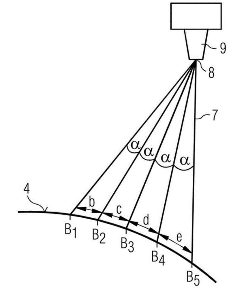
[0042] figure 2 and ...


PUM


Abstract

The invention relates to a method for marking a surface (3, 4, 6, 12) of a three-dimensional examination subject (1) with a projection device (2). The method includes the following steps: acquiring relief data (RD) of the surface (3, 4, 6, 12); establishing or defining a measurement information marking (5); determining a reference position value (v) that represents a position of a radiation device (8, 9) of the projection device relative to the surface (3, 4, 6, 12); calculating a pre-distortion of the established measurement information marking (5) depending on the relief data (RD) and the reference position value (v); and radiating pre-distorted measurement information marking (5) from the radiation device (8, 9) in the direction of the surface (3, 4, 6, 12). Moreover, the invention concerns a projection device (2) to implement such a method. The invention also concerns a medical technology imaging system (13) with such a projection device (2).

Description

technical field [0001] The invention relates to a method for marking the surface of a three-dimensional examination object, in particular the body surface of a patient. Furthermore, the invention relates to a projection device for carrying out such a method. Furthermore, the invention relates to a medical-technical imaging system having such a projection device. Background technique [0002] The determination of distances between defined points on a three-dimensional body is associated with increased effort when it comes to bodies with irregular, ie uneven and / or flexible surfaces. In the case of a human or animal body, the dimensions of the body surface can be changed, for example, by breathing or intestinal movements or by pressing onto certain surface parts. For percutaneous interventions on the body, for example with a needle or a scalpel, it is particularly important to precisely determine the dimensions on the body surface, ie on the skin. Therefore, the determinati...

Claims


Application Information

Patent Timeline
Patent Type & Authority Applications(China)
IPC IPC(8): A61B5/103G01B11/28
CPCA61B6/08A61B5/0077A61B6/022A61B5/103A61B6/488A61B6/5258A61B2090/366
Inventor A.豪索特E.罗思甘
Owner SIEMENS AG
Features
  • R&D
  • Intellectual Property
  • Life Sciences
  • Materials
  • Tech Scout
  • Unparalleled Data Quality
  • Higher Quality Content
  • 60% Fewer Hallucinations
Learn More