Cold hydrogenation wet-process dust removal slag slurry discharging system and method

A technology of wet dedusting and cold hydrogenation, applied in the direction of silicon halides, halosilanes, etc., can solve the problems of system shutdown, inability to shut down, loss of system liquid volume, etc., to improve system stability, reduce flow rate, and prolong service life and sealing effect

Active Publication Date: 2014-09-03
SICHUAN YONGXIANG POLY SILICON
View PDF4 Cites 2 Cited by
  • Summary
  • Abstract
  • Description
  • Claims
  • Application Information

AI Technical Summary

Problems solved by technology

However, since the slurry contains a large amount of silicon powder solids, under such a large pressure difference, the flow rate of the valve and the pipeline is very fast, and the ultra-fine silicon powder and chloride crystals in the slurry are likely to cause the sealing of the valve under high-speed flow. Lax or even impossible to close
Once the valve is not tightly sealed or cannot be related, the chlorosilane liquid in the wet dust removal system will be lost in large quantities, resulting in insufficient system liquid, resulting in system shutdown

Method used


Image

  • Cold hydrogenation wet-process dust removal slag slurry discharging system and method
  • Cold hydrogenation wet-process dust removal slag slurry discharging system and method
  • Cold hydrogenation wet-process dust removal slag slurry discharging system and method

Examples


Embodiment 1

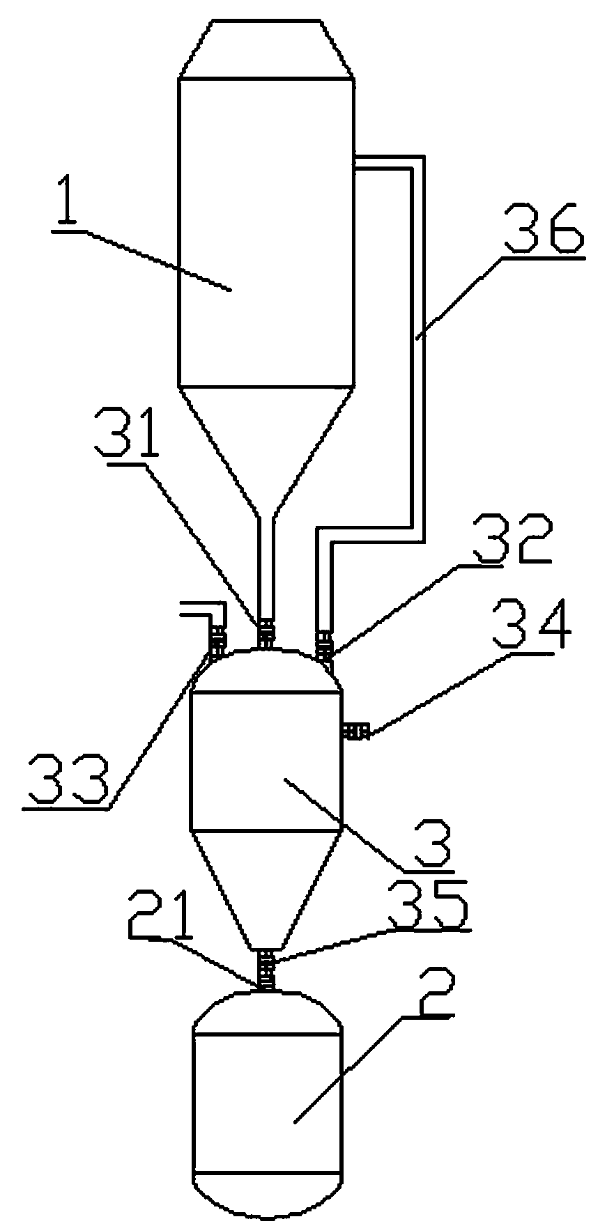
[0031] As a preferred embodiment of the present invention, with reference to the attached figure 2 , the present invention includes a washing tower 1 and a slurry treatment device 2, and is characterized in that: it also includes a slurry receiving tank 3, and the slurry receiving tank 3 is arranged between the washing tower 1 and the slurry treatment device 2; the slag The top of the slurry receiving tank 3 is provided with a slurry inlet valve 31, and the slurry inlet valve 31 is fixedly connected to the bottom of the washing tower 1; the top of the slurry receiving tank 3 is also provided with a balance valve 32 and a vent valve 33; The valve 32 is connected with one end of the balance pipeline 36, and the other end of the balance pipeline 36 is connected to the upper part of the washing tower 1; the bottom of the slurry receiving tank 3 is provided with a slurry outlet valve 35; the slurry outlet valve 43 is connected to the slurry receiving port 21 of the slurry treatmen...

Embodiment 2

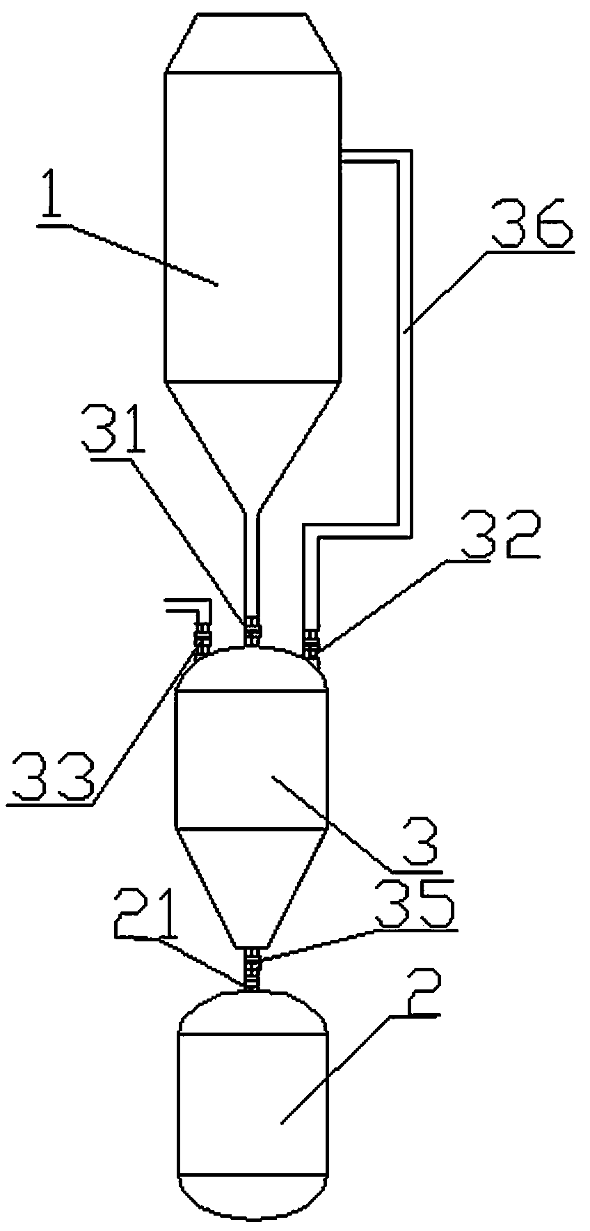
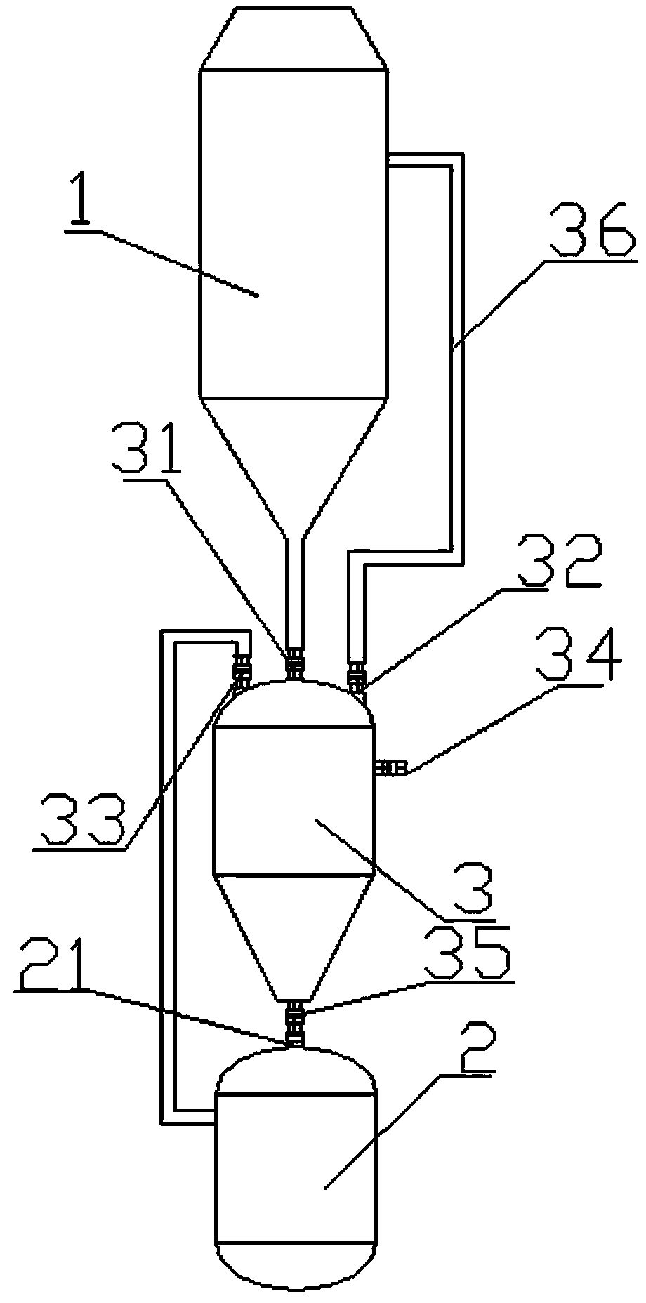
[0041] As a preferred embodiment of the present invention, with reference to the attached figure 1 and 4 , the present invention includes a washing tower 1 and a slurry treatment device 2, and is characterized in that: it also includes a slurry receiving tank 3, and the slurry receiving tank 3 is arranged between the washing tower 1 and the slurry treatment device 2; the slag The top of the slurry receiving tank 3 is provided with a slurry inlet valve 31, and the slurry inlet valve 31 is fixedly connected to the bottom of the washing tower 1; the top of the slurry receiving tank 3 is also provided with a balance valve 32 and a vent valve 33; The valve 32 is connected with one end of the balance pipeline 36, and the other end of the balance pipeline 36 is connected to the upper part of the washing tower 1; the bottom of the slurry receiving tank 3 is provided with a slurry outlet valve 35; the slurry outlet valve 43 is connected to the slurry receiving port 21 of the slurry tr...

Embodiment 3

[0053] As another preferred embodiment of the present invention, with reference to the attached figure 1 and 4 , the present invention includes a washing tower 1 and a slurry treatment device 2, and is characterized in that: it also includes a slurry receiving tank 3, and the slurry receiving tank 3 is arranged between the washing tower 1 and the slurry treatment device 2; the slag The top of the slurry receiving tank 3 is provided with a slurry inlet valve 31, and the slurry inlet valve 31 is fixedly connected to the bottom of the washing tower 1; the top of the slurry receiving tank 3 is also provided with a balance valve 32 and a vent valve 33; The valve 32 is connected with one end of the balance pipeline 36, and the other end of the balance pipeline 36 is connected to the upper part of the washing tower 1; the bottom of the slurry receiving tank 3 is provided with a slurry outlet valve 35; the slurry outlet valve 43 is connected to the slurry receiving port 21 of the slu...


PUM

PropertyMeasurementUnit
particle sizeaaaaaaaaaa

Abstract

The invention discloses a cold hydrogenation wet-process dust removal slag slurry discharging system and method, relating to the field of polysilicon cold hydrogenation dust removal equipment. The system comprises a washing tower and a slag slurry treatment device, and is characterized by also comprising a slag slurry receiving tank, wherein the slag slurry receiving tank is arranged between the washing tower and the slag slurry treatment device; the top end of the slag slurry receiving tank is provided with a slag slurry inlet valve; the slag slurry inlet valve is fixedly connected with the bottom of the washing tower; the top end of the slag slurry receiving tank is also provided with a balance valve and an emptying valve; and the bottom of the slag slurry receiving tank is provided with a slag slurry outlet valve. The bottom of the cold hydrogenation washing tower is provided with the slag slurry receiving tank, and the system pressure is relieved by using the slag slurry receiving tank instead of a disk valve, thereby reducing the system abrasion and lowering the failure rate.

Description

technical field [0001] The invention relates to the field of polysilicon production equipment, and more precisely relates to a cold hydrogenation wet dedusting slurry discharge system and a method thereof. Background technique [0002] At present, the mainstream technical route of polysilicon production is to improve Siemens, in which about 20 kg of silicon tetrachloride is produced by-product for every kilogram of polysilicon produced, and the by-product silicon tetrachloride is mainly transformed by the cold hydrogenation technology of silicon tetrachloride. The conversion process is mainly carried out in a cold hydrogenation reactor, and silicon powder needs to be added to the reactor at the same time as the conversion. As the reaction progresses, the silicon powder becomes smaller and is carried out by the reaction gas. The follow-up system generally uses wet dust removal to wash down the silicon powder, and the formed liquid slurry needs to be discharged from the sy...

Claims


Application Information

Patent Timeline
Patent Type & Authority Applications(China)
IPC IPC(8): C01B33/107
Inventor 刘汉元周奇李斌甘居富
Owner SICHUAN YONGXIANG POLY SILICON
Why Eureka
Try Eureka