
Fluid jet bed coal-to-synthetic gas gasification furnace

A coal-to-synthesis gas and gasifier technology, applied in the field of coal gasification, can solve the problems of increasing cost, affecting gasification effect, complicated operation, etc., and achieving the effects of increasing content, increasing heat transfer rate, and prolonging residence time

Active Publication Date: 2014-09-03
SHANGHAI YAOXING INVESTMENT MANAGEMENT
View PDF8 Cites 7 Cited by
  • Summary
  • Abstract
  • Description
  • Claims
  • Application Information

AI Technical Summary

Problems solved by technology

[0002] The traditional fluidized bed gasifier is usually a single-stage straight cylinder gasifier. In related technologies, pulverized coal is fed from the lower part of the gasifier, and the drying, pyrolysis, oxidation and gasification of pulverized coal are all carried out in the gasifier. The bottom is completed, resulting in the gasification agent, such as water vapor cannot be fully reacted and utilized, the hydrogen generated by the gasification reaction cannot be fully reacted to form methane, and the residence time of some pulverized coal particles in the gasifier is too short, etc.
However, the structure of the multi-layer fluidized bed gasifier is more complex and the operation is more complicated, which is not conducive to the long-term stable operation of the gasifier; raw coal and catalyst are added to each layer of fluidized bed, resulting in the temperature of each layer of fluidized bed is not easy control, which affects the gasification effect; moreover, it needs to use a catalyst, which increases the cost

Method used


Image

  • Fluid jet bed coal-to-synthetic gas gasification furnace

Examples


Embodiment Construction

[0031] Embodiments of the present invention are described in detail below, examples of which are shown in the drawings, wherein the same or similar reference numerals designate the same or similar elements or elements having the same or similar functions throughout. The embodiments described below by referring to the figures are exemplary and are intended to explain the present invention and should not be construed as limiting the present invention.

[0032] In describing the present invention, it is to be understood that the terms "upper", "lower", "top", "bottom", "inner", "outer", "axial", "radial", "circumferential" The orientation or positional relationship indicated by etc. is based on the orientation or positional relationship shown in the drawings, and is only for the convenience of describing the present invention and simplifying the description, rather than indicating or implying that the referred device or element must have a specific orientation, use a specific Azi...


PUM


Abstract

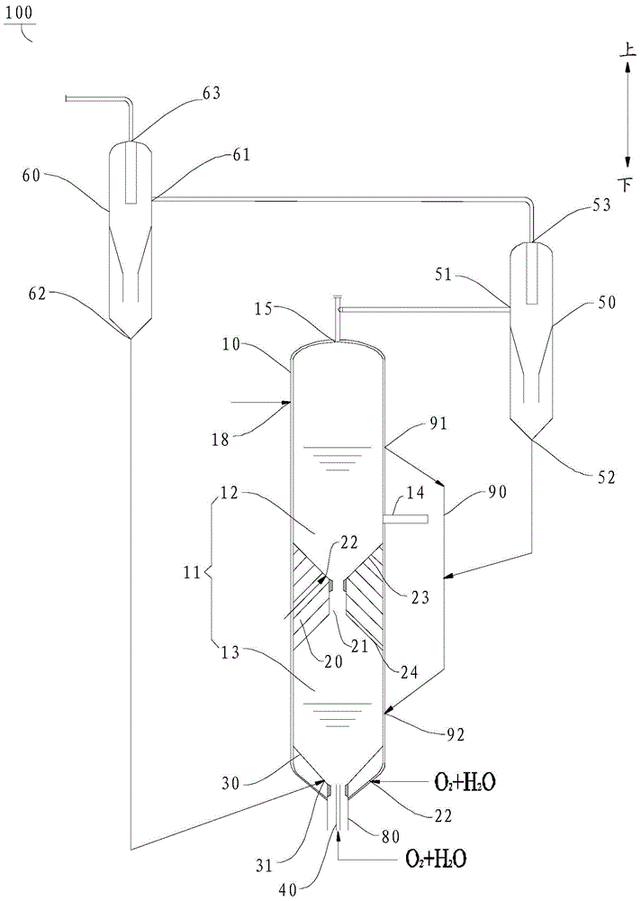
The invention discloses a fluid jet bed coal-to-synthetic gas gasification furnace which comprises a furnace body, a spacer bush, an overflow pipe, a gas distribution plate and a center pipe, wherein a cavity is formed in the furnace body; the spacer bush is arranged in the cavity to divide the cavity into an upper cavity and a lower cavity; the overflow pipe is arranged at the outer side of the furnace body, one end of the overflow pipe is communicated with an inlet of the overflow pipe, and the other end of the overflow pipe is communicated with an outlet of the overflow pipe; the gas distribution plate is arranged in the lower cavity, and a slag discharge pipe which protrudes out of the lower cavity and discharges slag inside the lower cavity is arranged at the bottom of the gas distribution plate. According to the fluid jet bed coal-to-synthetic gas gasification furnace, the upper cavity and the lower cavity both form fluid jet beds, and the upper cavity and the lower cavity are communicated through a through hole; a solid material enters the upper cavity of the gasification furnace and then sufficiently contacts with a gasification agent and a synthetic gas, and the retention time of the solid material in the gasification furnace is prolonged, so that the methane (CH4) content, steam decomposition rate and carbon transformation rate of the synthetic gas are increased.

Description

technical field [0001] The invention relates to coal gasification technology, in particular to a jet bed coal-made synthesis gas gasification furnace. Background technique [0002] The traditional fluidized bed gasifier is usually a single-stage straight cylinder gasifier. In related technologies, pulverized coal is fed from the lower part of the gasifier, and the drying, pyrolysis, oxidation and gasification of pulverized coal are all carried out in the gasifier. The bottom is completed, resulting in gasification agents, such as water vapor cannot be fully reacted and utilized, the hydrogen generated by the gasification reaction cannot be fully reacted to form methane, and the residence time of some pulverized coal particles in the gasifier is too short. However, the structure of the multi-layer fluidized bed gasifier is more complex and the operation is more complicated, which is not conducive to the long-term stable operation of the gasifier; raw coal and catalyst are add...

Claims


Application Information

Patent Timeline
IPC IPC(8): C10J3/56C10J3/84
Inventor 吴龙周琦杨守青刘斌周大鹏李冬阳冯立根
Owner SHANGHAI YAOXING INVESTMENT MANAGEMENT
Learn More