Hydraulic lifting building scaffold

A hydraulic lifting and scaffolding technology, which is applied to scaffolding supported by house structures, buildings, building structures, etc., can solve the problems of large one-time investment, large material consumption, low safety performance, etc., and achieve labor intensity reduction, simple operation, The effect of excellent structural strength and hardness

Active Publication Date: 2014-09-03
江苏溧阳建设集团有限公司
View PDF6 Cites 1 Cited by
  • Summary
  • Abstract
  • Description
  • Claims
  • Application Information

AI Technical Summary

Problems solved by technology

[0002] Traditional scaffolding is generally built from the ground with steel pipe fasteners and other materials until it is capped with the building. In the construction of high-rise buildings, this structure not only needs to consume a lot of materials, but also requires a large one-time investment and a long construction period. long, less safe
In recent years, in order to overcome the shortcomings of traditional scaffolding, some new improvements have emerged, such as lifting scaffolding, which is used to overcome the shortcomings of traditional scaffolding from the ground to the top of the building, and fix the scaffolding on the pillars, walls or On the beam, but as the fastening bolts for fixing the scaffolding, etc., they are consumable parts that need to be checked and replaced frequently, which not only takes time and labor, but also often delays the construction period
In addition, the building scaffolding in the prior art is usually made of ordinary low-carbon steel, and its overall structural strength, especially welding strength, etc. also needs to be improved, in order to further improve the safety factor of high-rise building construction

Method used


Image

  • Hydraulic lifting building scaffold
  • Hydraulic lifting building scaffold

Examples


Embodiment 1

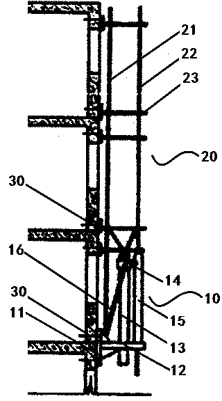
[0018] as attached figure 1 As shown, the hydraulic lifting type construction scaffold described in this embodiment is composed of a hydraulic lifting mechanism 10 and a scaffolding structure 20, and the hydraulic lifting mechanism 10 and the scaffolding structure 20 are fixed to the wall by locking bolts 30; Described scaffolding structure 20 mainly is made of inner tripod bar 21, outer tripod bar 22 and a plurality of cantilever beams 23; Described cantilever beam 23 is fixed on described inner tripod bar 21 and outer tripod bar 22 and extends to the wall body, and fixed to the wall by locking bolts 30; the hydraulic lifting mechanism 10 includes a support base plate 11, a support beam 12 and a hydraulic cylinder 13 with a telescopic rod; the support beam 12 is welded on the support base plate 11 above, and the hydraulic cylinder 13 is arranged in the middle of the support beam 12; the outer end of the support beam 12 is provided with a guide column 15, and the upper end of ...

Embodiment 2

[0020] In this embodiment, the scaffold structure material is made of low-carbon steel, because low-carbon steel can provide good welding performance; however, in order to further improve the safety factor of the scaffold structure, especially the safety under low temperature conditions coefficient, it is also necessary to improve the toughness or low-temperature weldability of the low-carbon steel, for which the following solutions are provided in this embodiment:

[0021] In order to ensure economical efficiency, the low-carbon steel described in this example adopts the design idea of ​​low-carbon and low-silicon, and prepares a low-carbon steel with excellent comprehensive properties; it not only ensures the mechanical properties required by the steel, but also has excellent Excellent low temperature toughness and welding performance. For this reason, the low-carbon steel described in this embodiment is to heat the following steel materials to 1000~1080°C, and finish hot ro...

Embodiment 3

[0031]In this embodiment, in order to avoid frequent inspection and replacement of the locking bolt, the locking bolt is made of a hard steel base and a hardened coating. Wherein, the hard steel matrix contains: C: 0.20~0.25%, Si: 0.05~0.15%, Mn: 1.25~1.50%, Ni: 0.42~0.70%, Cr: 1.08~1.25%, Cu: 0.03~ 0.08%, Al: 0.05~0.08%, Mg: 0.005~0.010%, B: 0.001~0.005%, N≤0.01%, P≤0.025%, S≤0.01%, and the balance is Fe and unavoidable impurities. The hard steel is cast according to a conventional method, and then hot-processed to form a hard steel matrix; then, plasma nitriding is performed on the hard steel matrix, and the nitriding temperature is 520-540°C and the surface layer of the hard steel matrix is Form a nitrided layer with a thickness of 100-150 microns in the nitrided layer, and the concentration of nitrogen in the nitrided layer is 7.5-8.0wt%; then spray a composite coating (such as thermal spraying or cold spraying) on ​​the surface of the nitrided layer, heat To 500~520°C, h...


PUM


Abstract

The invention relates to a hydraulic lifting building scaffold which is formed by a hydraulic lifting mechanism and a scaffold structure made of low-carbon steel. The hydraulic lifting mechanism and the scaffold structure are fixed with a wall through a locking bolt, and the scaffold structure is mainly formed by an inner scaffold rod, an outer scaffold rod and a plurality of cantilever beams. The cantilever beams are fixed on the inner scaffold rod and the outer scaffold rod and extend to the wall and are fixed with the wall through a locking bolt. The hydraulic lifting mechanism comprises a support base plate, a support beam, a hydraulic oil cylinder and an electronic control cabinet, wherein the hydraulic oil cylinder is provided with a telescopic rod. The support beam is welded to the support base plate, and the hydraulic oil cylinder is arranged in the middle of the support beam. The hydraulic lifting building scaffold is suitable for construction of high-rise building structure engineering.

Description

technical field [0001] The invention relates to the technical field of mechanical equipment used in building construction, and more specifically, the invention relates to a hydraulic lifting type construction scaffold used on beams of high-rise buildings. Background technique [0002] Traditional scaffolding is generally built from the ground with steel pipe fasteners and other materials until it is capped with the building. In the construction of high-rise buildings, this structure not only needs to consume a lot of materials, but also requires a large one-time investment and a long construction period. Longer and less secure. In recent years, in order to overcome the shortcomings of traditional scaffolding, some new improvements have emerged, such as lifting scaffolding, which is used to overcome the shortcomings of traditional scaffolding from the ground to the top of the building, and fix the scaffolding on the pillars, walls or On the beam, but as the fastening bolts f...

Claims


Application Information

Patent Timeline
Patent Type & Authority Applications(China)
IPC IPC(8): E04G3/28
Inventor 吕永武陈建林龚向军
Owner 江苏溧阳建设集团有限公司
Why Eureka
Try Eureka