Bimetal composite pipe and manufacturing process thereof

A bimetallic composite pipe and process technology, which is applied in the direction of manufacturing tools, metal processing equipment, pipes, etc., can solve the problems of poor surfacing welding quality and difficult surfacing welding, and achieve the effect of ensuring the quality of welding construction

Active Publication Date: 2014-09-03
XIAN SUNWARD AEROSPACE MATERIAL CO LTD
View PDF8 Cites 15 Cited by
  • Summary
  • Abstract
  • Description
  • Claims
  • Application Information

AI Technical Summary

Problems solved by technology

The base pipe of the bimetal clad pipe after explosive cladding is flush with the end of the liner pipe, so it is difficult to carry out surfacing welding, and the quality of surfacing welding is not good

Method used


Image

  • Bimetal composite pipe and manufacturing process thereof

Examples


Embodiment 1

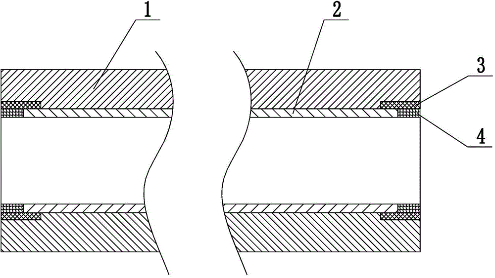
[0028] Such as figure 1 The shown bimetallic composite pipe includes a base pipe 1 and an inner liner 2 sleeved inside the base pipe 1, the length of the inner liner 2 is shorter than the length of the base pipe 1, and the two ends of the base pipe 1 Annular grooves are provided on the inner walls, and a first surfacing layer 3 is welded in the annular grooves. The inner diameter of the first surfacing layer 3 is the same as that of the base pipe 1. The first surfacing layer 3 A second overlay 4 is welded on the inner wall of the inner lining pipe 2, the end of the second overlay 4 is flush with the end of the base pipe 1, and the second overlay 4 The inner diameter of the inner liner pipe 2 is the same, and the depth of the second surfacing layer 4 along the axial direction of the bimetallic composite pipe is smaller than the depth of the annular groove along the axial direction of the bimetallic composite pipe.

[0029] In this embodiment, the depth of the annular groove al...

Embodiment 2

[0042] This embodiment is the same as Embodiment 1, except that the depth of the annular groove along the axial direction of the bimetallic composite pipe is 40 mm, and the depth of the annular groove perpendicular to the axial direction of the bimetallic composite pipe is 3 mm. The depth of the second surfacing layer 4 along the axial direction of the bimetal composite pipe is 20 mm.

Embodiment 3

[0044] This embodiment is the same as Embodiment 1, except that the depth of the annular groove along the axial direction of the bimetallic composite pipe is 60 mm, and the depth of the annular groove perpendicular to the axial direction of the bimetallic composite pipe is 2.5 mm. , the depth of the second surfacing layer 4 along the axial direction of the bimetal composite pipe is 30 mm.

[0045] The bimetallic composite pipe of the present invention can ensure the effective compounding of the base pipe and the inner liner pipe end by opening annular grooves on the inner walls of both ends of the base pipe, and welding the first overlay welding layer in the annular grooves, thereby ensuring that the bimetal The lining pipe of the composite pipe is not affected by the base pipe during the girth welding process, which ensures the welding construction quality of the thin-walled stainless steel lining.


PUM

PropertyMeasurementUnit
depthaaaaaaaaaa
depthaaaaaaaaaa
depthaaaaaaaaaa

Abstract

The invention discloses a bimetal composite pipe which comprises a base pipe and a lining pipe installed on the inner side of the base pipe in a sleeved mode. The lining pipe is shorter than the base pipe, the inner walls of the two ends of the base pipe are respectively provided with an annular groove, each annular groove is internally provided with a first surfacing layer in a welded mode, the internal diameter of each first surfacing layer is the same as that of the base pipe, a second surfacing layer is welded to the inner wall of each first surfacing layer and located at the end of the lining pipe, the ends of the second surfacing layers are flush with the end of the base pipe, and the internal diameter of each second surfacing layer is the same as that of the lining pipe. The invention further discloses a manufacturing process of the bimetal composite pipe. According to the bimetal composite pipe, the annular grooves are formed in the inner walls of the two ends of the base pipe and the first surfacing layers are welded to the annular grooves, the end of the base pipe and the end of the lining pipe can be compounded effectively, and it is ensured that the lining pipe of the bimetal composite pipe is not affected by the base pipe in the circular welding process.

Description

technical field [0001] The invention belongs to the technical field of metal tubular products, and in particular relates to a bimetal composite pipe and a manufacturing process thereof. Background technique [0002] Metal pipelines have been widely used in oil and gas transportation, and carbon steel pipes are the most widely used, but their corrosion resistance is poor. Among the corrosion-resistant alloy pipes, bimetallic composite pipes have been widely used in oil and gas pipelines because of their superior mechanical properties, good corrosion resistance, and strong weldability. [0003] At present, the bimetallic composite pipe is mainly prepared by the explosive composite method, that is, the base pipe and the liner pipe are assembled, and then the cluster explosive is placed on the axis of the liner pipe, and the explosive force produced by the explosive instantly causes the water pressure in the tank to increase instantaneously. The instantaneously increased water ...

Claims


Application Information

Patent Timeline
Patent Type & Authority Applications(China)
IPC IPC(8): F16L9/02B23K33/00B23P15/00
CPCB21C37/06F16L9/02
Inventor 吴泽袁江龙李奇虞明星黄晓华张燕飞
Owner XIAN SUNWARD AEROSPACE MATERIAL CO LTD
Why Eureka
Try Eureka