Vapor generator

A technology of a steam generator and a heating pipe is applied in the field of kitchen utensils and can solve the problems of low utilization rate of heat energy of the steam generator and the like

Inactive Publication Date: 2014-09-03
浙江哈能厨房设备有限公司
View PDF8 Cites 2 Cited by
  • Summary
  • Abstract
  • Description
  • Claims
  • Application Information

AI Technical Summary

Problems solved by technology

[0005] Since the fuel ejected from the burner burns in the hollow heating inner tank, and when the inner wall of the heating inner tank is heated, the connecting pipe is still heated, thereby increasing the heating area to improve the utilization rate of heat energy; wherein, Most of the heat energy generated by fuel combustion is transferred to the connecting pipe, and transferred to the steam generating chamber through the heated inner tank; the remainin

Method used


Image

  • Vapor generator
  • Vapor generator
  • Vapor generator

Examples


Embodiment 1

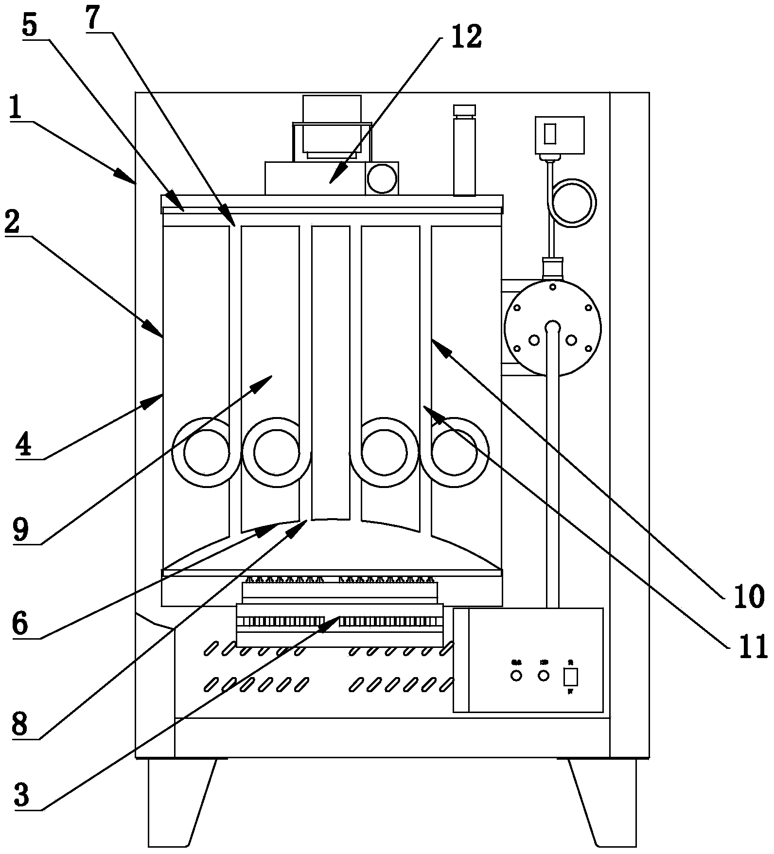
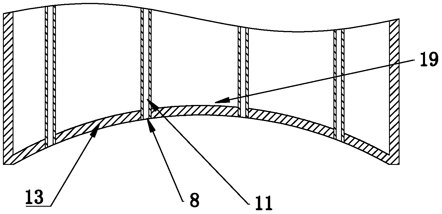
[0038] In Embodiment 1, the heating surface 6 is an arc-shaped heating surface 13 , and the arc-shaped heating surface 13 includes a protruding portion 19 , and the protruding portion 19 is disposed toward the side of the upper hole 7 .

[0039] The arc-shaped heating surface 13 is curved toward the upper hole 7, so it is arc-shaped. Since the area of ​​the arc-shaped surface is larger than the area of ​​the plane, the area of ​​the arc-shaped heating surface 13 is larger. When the flame generated by the burner 3 acts on the arc-shaped heating surface 13, can effectively increase the heating area, and also has the effect of uniform heating.

Embodiment 2

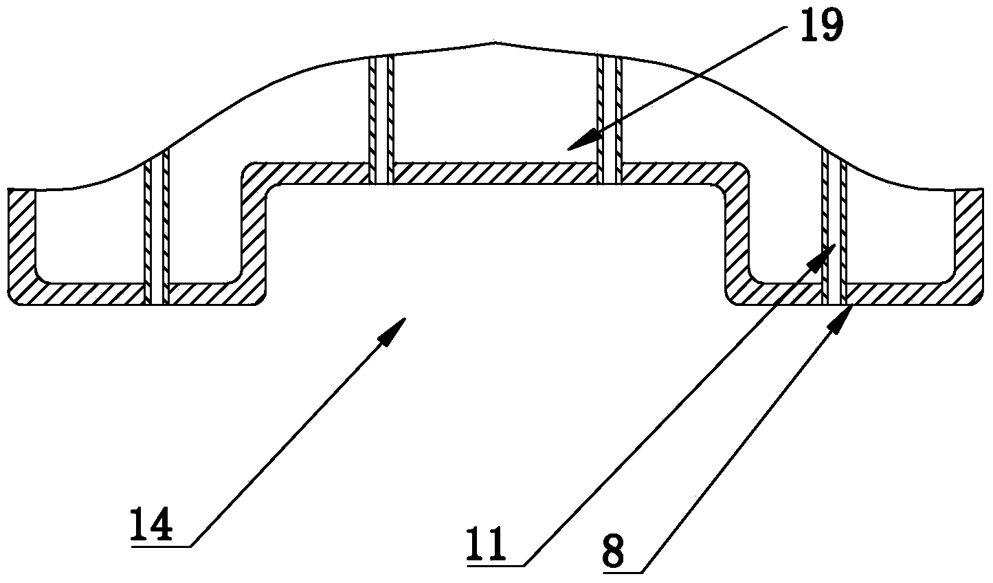
[0040] In the second embodiment, the heating surface 6 is a stepped heating surface 14, and the stepped heating surface 14 includes a protruding portion 19, and the protruding portion 19 is arranged toward the upper hole 7 side.

[0041] Since the heating surface 6 is continuously folded toward the upper hole 7 and is stepped, the area of ​​the stepped heating surface 14 is larger than that of the plane. When the flame generated by the burner 3 acts on the stepped heating surface 14, it can effectively increase the heating area, and also has the effect of uniform heating.

Embodiment 3

[0042] In the third embodiment, the heating pipe 10 is a spiral heating pipe 15, the water tank 2 is cylindrical, and the spiral heating pipe 15 is provided with a spiral part 16 spiraling around the axis of the water tank 2 inside the water tank 2.

[0043] Since the helical part 16 is spirally formed on the helical heating tube 15, the helical part 16 can increase the contact area between the helical heating tube 15 and the water, thereby effectively heating the water in the accommodating chamber 9, and prolonging the length of the hot air channel 11 to increase the temperature of the high-temperature air. The residence time in the hot air channel 11, so that the high temperature air has enough time to transfer heat; when the water tank 2 is in the shape of a barrel, and the heating pipe 10 is a spiral heating pipe 15, the spiral part 16 is spirally arranged around the axis, The axis of the spiral portion 16 is arranged coaxially with the axis of the water tank 2. When the ra...


PUM


Abstract

The invention discloses a vapor generator. The vapor generator comprises a generator body comprising a machine frame, a water tank and a combustor, wherein the water tank and the combustor are arranged in the machine frame, the water tank is connected with a water inlet pipe and a vapor outlet pipe and comprises a tank body and a tank cover connected to the tank body, the combustor is arranged corresponding to the tank body comprising a heating surface, the combustor is arranged towards the heating surface, the tank cover is provided with an upper hole, the heating surface is provided with a lower hole, a containing cavity in which a heating pipe is arranged is formed in the water tank, one end of the heating pipe plugs the upper hole, the other end of the heating pipe plugs the lower hole, and hot vapor channels communicated with one another are arranged in the heating pipe. The vapor generator has the advantage of being high in heat energy use ratio.

Description

technical field [0001] The invention relates to the technical field of kitchen utensils, more specifically, it relates to a steam generator. Background technique [0002] A steam generator is a mechanical device that uses fuel or other energy to heat water into steam. It can provide high-temperature steam for various steam-heated kitchen cooking equipment. It is widely used in steaming and stewing in the catering industry, such as: steaming vegetables, Steam rice, cook porridge, cook soy milk, stew soup. [0003] Steam generators are generally divided into two types of steam generators: electric heating and fuel heating according to their heating methods; most of the steam generators currently used in the field of kitchen utensils use liquefied gas or natural gas to heat water. Water is heated into steam. The advantages of this steam generator are fast heating speed and large steam output, which can provide steam to multiple equipments. The disadvantage is that the steam ou...

Claims


Application Information

Patent Timeline
IPC IPC(8): F22B31/08F22B37/00
Inventor 章霄君
Owner 浙江哈能厨房设备有限公司
Why Eureka
Try Eureka