
Novel heat exchanger

A heat exchanger, a new type of technology, applied in the direction of heat exchanger types, indirect heat exchangers, heat exchange equipment, etc., can solve the problems affecting the heat exchange efficiency, transfer to the inner tube, etc., to achieve good heat exchange capacity and novel appearance , Improve the effect of heat exchange efficiency

Inactive Publication Date: 2014-09-03
KUNSHAN RUIHENGFENG TECH CONSULTING
View PDF6 Cites 3 Cited by
  • Summary
  • Abstract
  • Description
  • Claims
  • Application Information

AI Technical Summary

Problems solved by technology

[0003] According to the heat transfer principle, heat exchangers can be divided into surface heat exchangers, regenerative heat exchangers, fluid connection indirect heat exchangers, and direct contact heat exchangers; according to their uses, they can be divided into heaters, preheaters, Superheater, evaporator; According to the structure of the heat exchanger, it can be divided into floating head heat exchanger, fixed tube-sheet heat exchanger, U-shaped tube-sheet heat exchanger, plate heat exchanger, etc.; the existing heat exchangers are generally They are all composed of inner and outer concentric tubes. Two spaces are formed between the inner tube and the inner tube and the outer wall, and two kinds of temperature media are respectively passed through, and exchanges are carried out during the flow process. In order to improve the heat transfer efficiency of the heat exchanger, people will exchange The tube bundles of the heater are designed in various shapes to increase the heat exchange area and achieve the purpose of improving the heat exchange rate. However, during the heat exchange process, the heat absorbed by the outer tube cannot directly transfer the heat to the inner tube, thus affecting the heat exchange. efficiency

Method used


Image

  • Novel heat exchanger
  • Novel heat exchanger
  • Novel heat exchanger

Examples


Embodiment Construction

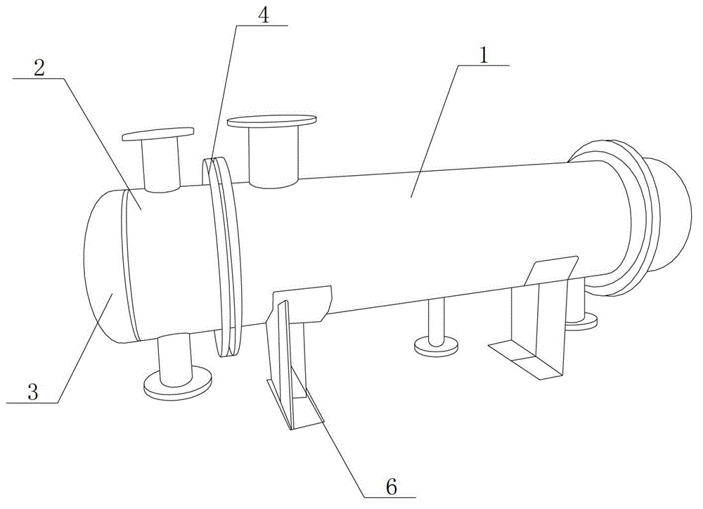
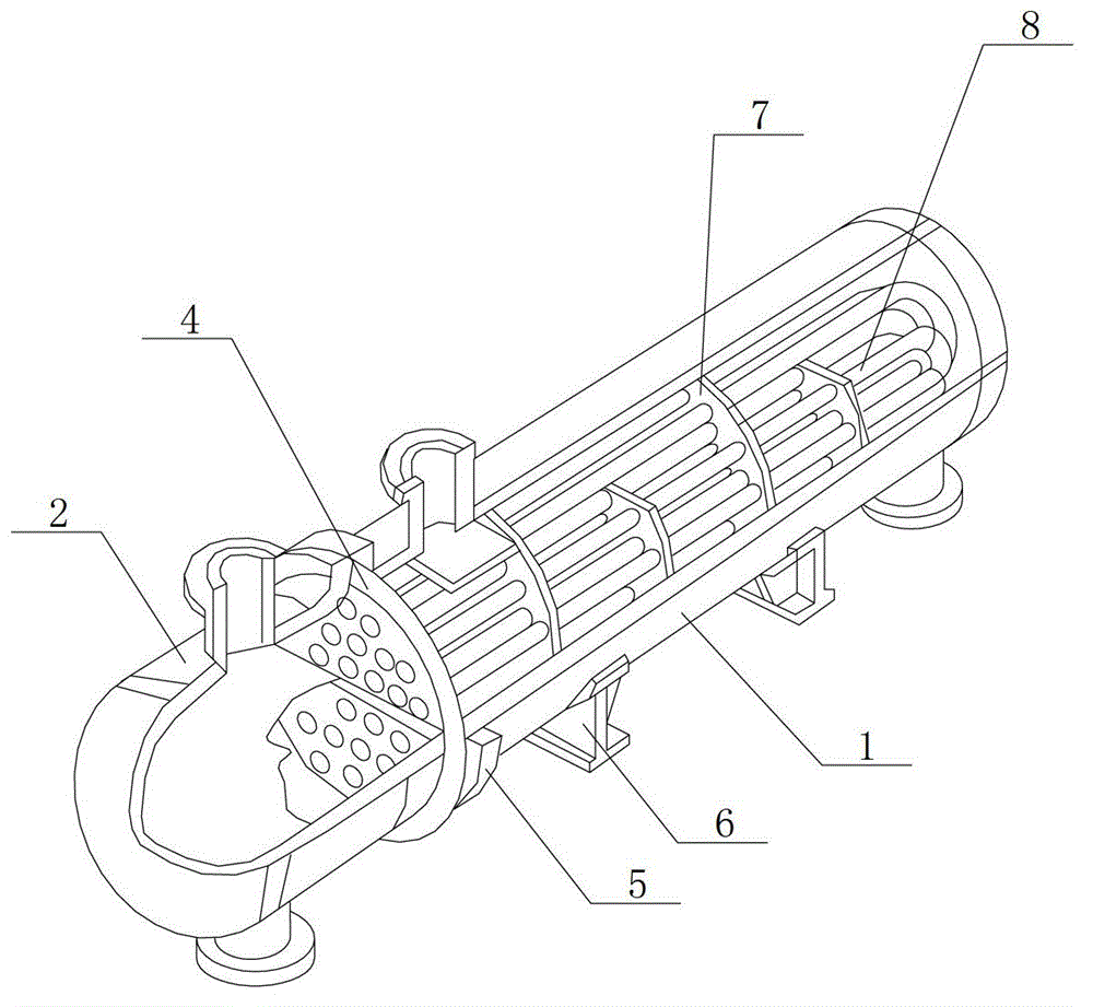
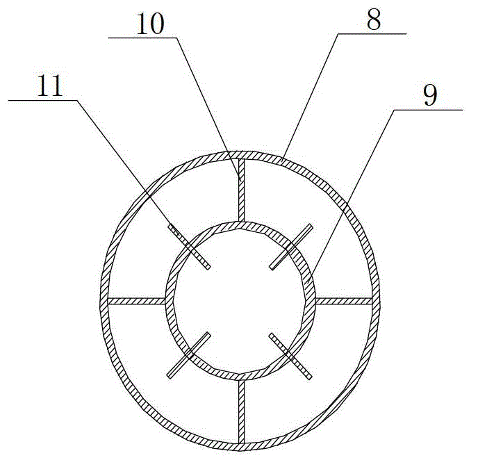
[0011] Reference Figure 1-Figure 3 , This specific embodiment adopts the following technical solutions: it is composed of shell 1, tube box 2, tube box cover 3, tube plate 4, flange 5, support 6, baffle 7, outer tube 8, inner tube 9 , Support body 10, heat exchange fins 11; one end of the shell 1 is provided with a tube box 2, one side of the tube box 2 is provided with a tube box cover 3, the other side of the tube box 2 is provided with a tube plate 4, tube plate A flange 5 is provided on one side of 4, a plurality of supports 6 are uniformly provided on the bottom of the housing 1, a baffle 7 and an outer tube 8 are provided inside the other end of the housing 1, and an inner tube is provided in the outer tube 8 9, and the annular space formed between the outer tube 8 and the inner tube 9 is axially provided with a support body 10, and a plurality of heat exchange fins 11 are uniformly provided on the tube wall of the inner tube 9 in the axial direction.

[0012] The casing ...


PUM


Abstract

The invention provides a novel heat exchanger, and relates to the technical field of heat exchange and refrigeration air conditioner mechanical equipments. One end of a shell (1) is provided with a tube box (2), and a tube box cover (3) is arranged on one side of the tube box (2). A tube plate (4) is arranged on the other side of the tube box (2), and a flange (5) is arranged on one side of the tube plate (4). A plurality of supports (6) are evenly arranged at the bottom of the shell (1), and a baffle plate (7) and an outer tube (8) are arranged in the other end of the shell (1). An inner tube (9) is arranged in the outer tube (8), a supporting body (10) is axially arranged in a loop space formed by the outer tube (8) and the inner tube (9), and a plurality of heat exchange fins (11) are evenly arranged in the axial direction on the wall of the inner tube (9). The novel heat exchanger is reasonable in structural design, novel in appearance, convenient to produce, capable of achieving the good heat exchange capacity and improving the heat exchange efficiency, and applicable to the fields of the chemical industry, the pharmacy and the like.

Description

Technical field: [0001] The invention relates to the technical field of heat exchange and refrigeration and air-conditioning mechanical equipment, in particular to a new type of heat exchanger. Background technique: [0002] The heat exchanger is a device that transfers part of the heat of the hot fluid to the cold fluid. It is also called a heat exchanger. The heat exchanger is a general equipment in the chemical, petroleum, power, food and many other industrial sectors, and it occupies an important position in production. In chemical production, heat exchangers can be used as heaters, coolers, condensers, evaporators and reboilers, etc., and are more widely used. There are many types of heat exchangers, but they are basically based on the principle and method of heat exchange between cold and hot fluids. It can be divided into three categories: partition type, hybrid type and heat storage type. Among the three types of heat exchangers, partition type heat exchangers are the mos...

Claims


Application Information

Patent Timeline
IPC IPC(8): F28D7/06F28D7/10F28F1/42
CPCY02P20/10
Inventor 沈亮亮
Owner KUNSHAN RUIHENGFENG TECH CONSULTING
Learn More