Fine metal wire drawing unit

A metal wire drawing and metal wire technology, applied in metal wire drawing, metal extrusion, metal processing equipment, etc., can solve the problems of insufficient wire drawing toughness, poor wire drawing effect, insufficient cooling and cleaning, etc., and achieve reasonable production cost and high degree of automation , making simple effects

Active Publication Date: 2014-09-10
柳城县鼎铭金属制品有限公司
View PDF6 Cites 10 Cited by
  • Summary
  • Abstract
  • Description
  • Claims
  • Application Information

AI Technical Summary

Problems solved by technology

[0006] Aiming at the shortcomings of insufficient cooling and cleaning, poor drawing effect and insufficient drawing toughness existing in the existing metal wi

Method used


Image

  • Fine metal wire drawing unit
  • Fine metal wire drawing unit
  • Fine metal wire drawing unit

Examples


Embodiment 1

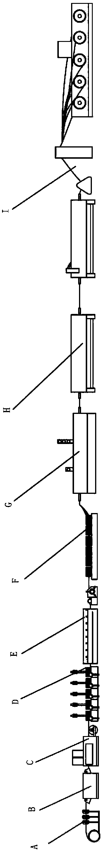
[0050] Such as figure 1 As shown, the fine metal wire drawing unit is composed of eight equipment arranged in sequence, the metal wire rod straightening device A, the metal wire coating equipment B, the metal wire drying equipment C, the first metal wire drawing equipment D, the first metal wire drawing equipment A metal wire cleaning device E, a second metal wire drawing device F, a second metal wire cleaning device G, a metal wire annealing device J, and a metal wire cooling drum wire receiving device I.

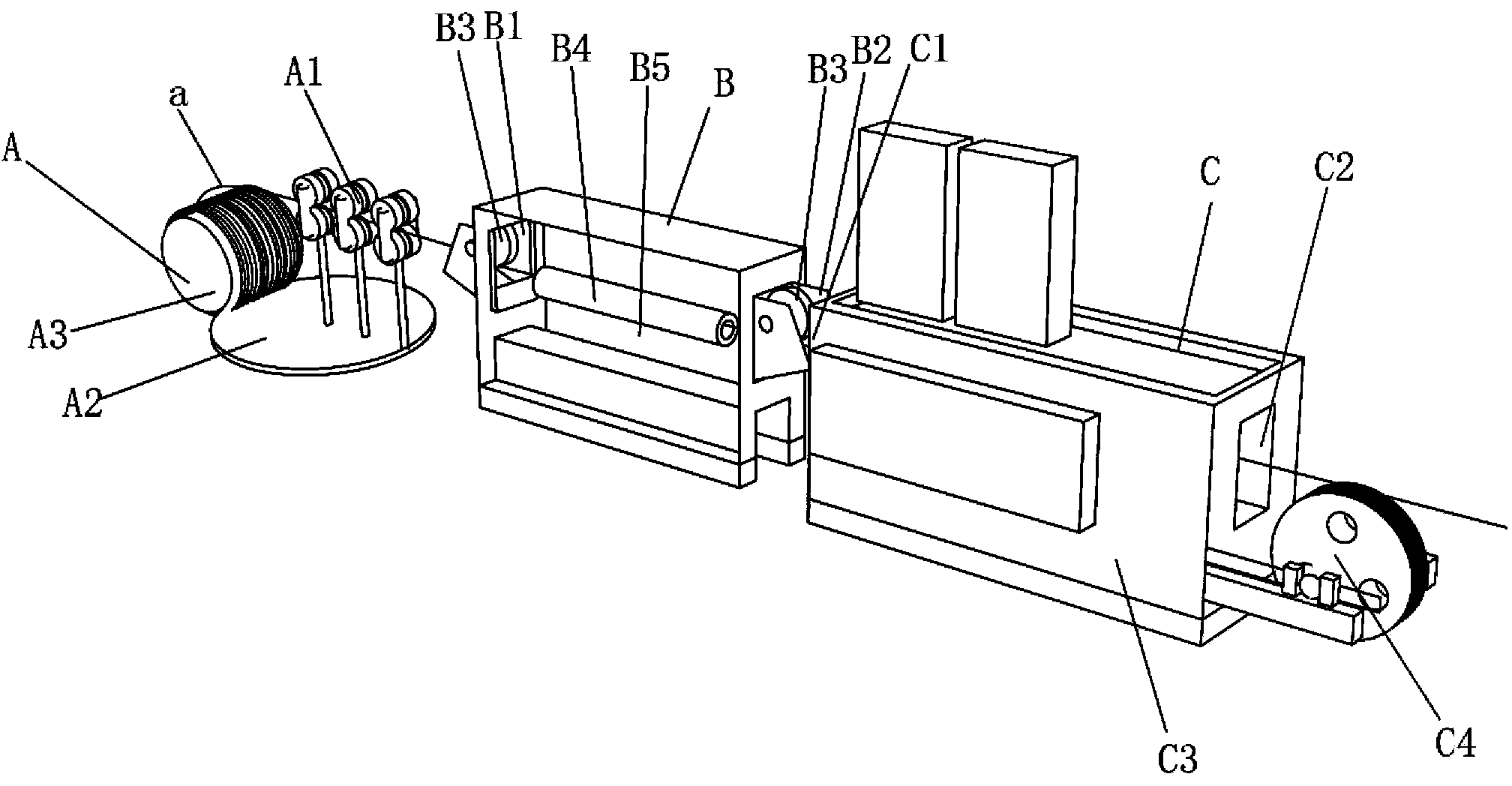
[0051] Such as figure 2 As shown, the metal wire rod straightening device A includes a metal wire rod holder A3, the metal wire rod is wound on the metal wire rod holder A3, and a plurality of sets of metal rods are arranged on the side of the metal wire rod holder A3. The pair of rollers A1, the metal wire rod creel A3 and the metal pair of rollers A1 are set on the supporting platform A2, and the metal wire rod becomes a thick-diameter wire a after being straightened b...

Embodiment 2

[0065] In this embodiment, the difference from Embodiment 1 is that the bottom of the cooling water pool I5 is inclined 30 degrees to the metal wire collection equipment. The rest of the working principles are the same as in Embodiment 1.

[0066] In addition, since the bottom surface angle of the cooling water pool I5 belongs to the category easily understood by those skilled in the art, no detailed description will be given here.


PUM

PropertyMeasurementUnit
Diameteraaaaaaaaaa

Abstract

The invention relates to a fine metal wire drawing unit. The fine metal wire drawing unit comprises a metal wire rod straightening device (A), metal wire coating equipment (B), metal wire drying equipment (C), first metal wire drawing equipment (D), first metal wire cleaning equipment (E), second metal wire drawing equipment (F), second metal wire cleaning equipment (G), metal wire annealing equipment (H) and metal wire cooling drum wire withdrawing equipment (I) arranged in sequence, wherein after metal wire rods are passed by the metal wire rod straightening device (A), the metal wire coating equipment (B), the metal wire drying equipment (C), the first metal wire drawing equipment (D), the first metal wire cleaning equipment (E), the second metal wire drawing equipment (F), the second metal wire cleaning equipment (G) and the metal wire annealing equipment (H), the metal wire rods are connected with the metal wire cooling drum wire withdrawing equipment (I) for realizing wire withdrawal.

Description

technical field [0001] The invention relates to a metal wire drawing equipment, in particular to a fine metal wire drawing unit. Background technique [0002] The wire drawing process is a metal processing process. In metal pressure processing. Under the action of external force, the metal is forced to pass through the mold, the cross-sectional area of ​​the metal is compressed, and the technical processing method to obtain the required cross-sectional area shape and size is called the metal wire drawing process. make it change shape. The size of the tool is called a drawing die. The general metal wire drawing process includes the steps of metal wire rod straightening, gold, drying, cooling and cleaning, metal wire drawing, and wire collection. For the straightening of wire rods with thinner metal diameters, special straightening processes are required. We retrieved many documents of metal wire drawing equipment, but there are many defects, such as: [0003] 1. Chinese ...

Claims


Application Information

Patent Timeline
IPC IPC(8): B21C1/02B21C19/00B21C9/00B21C43/02C21D9/52
Inventor 张瑞杰
Owner 柳城县鼎铭金属制品有限公司
Why Eureka
Try Eureka