Laser Marking System
A technology of laser marking and laser head, which is applied in laser welding equipment, printing, printing devices, etc., can solve the problems of high price and high price of light control and intelligent central control system, and achieve the effect of simplifying structure and reducing manufacturing cost
- Summary
- Abstract
- Description
- Claims
- Application Information
AI Technical Summary
Problems solved by technology
Method used
Image


Examples
Embodiment 1
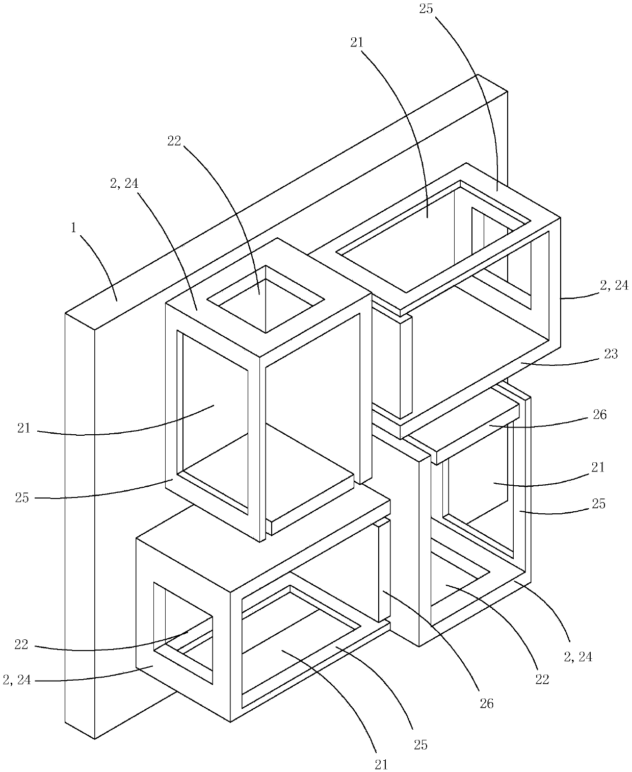
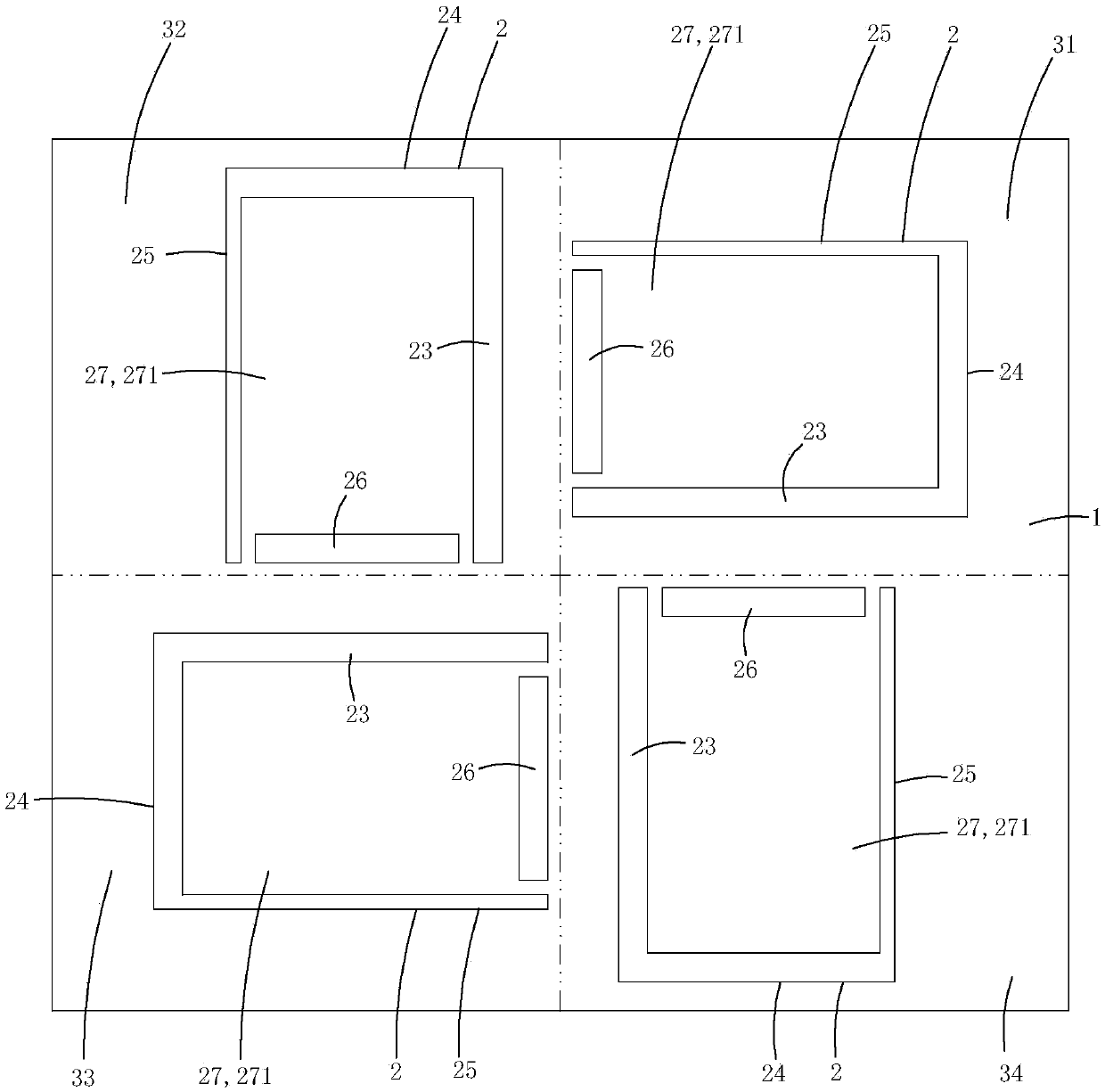
[0017] Figure 1 to Figure 3 A specific embodiment of the invention is shown in which, figure 1 It is a schematic diagram of a three-dimensional structure of the first structure of the present invention; figure 2 yes figure 1 A schematic diagram of a three-dimensional structure of the laser marking system shown when viewed from another angle; image 3 yes figure 1 A working schematic diagram of the laser marking system shown.
[0018] This embodiment is a laser marking system, see Figure 1 to Figure 3 As shown, it includes a laser head (not shown in the figure) that emits a plane laser, a drive disc 1 that performs circular motion, and four clamps 2 arranged on the drive disc. See image 3 As shown, the plane where the driving disc is located is divided into four stations by dotted lines, along the direction of rotation of the driving disc, there are feeding station 31, first marking station 32, second marking station 33 and discharging station 34; Each fixture is pro...
Embodiment 2
[0028] Figure 4 to Figure 7 Another embodiment of the invention is shown, wherein, Figure 4 It is a schematic diagram of a three-dimensional structure of the second structure of the present invention; Figure 5 yes Figure 4 A schematic diagram of a three-dimensional structure of the laser marking system shown when viewed from another angle; Figure 6 yes Figure 4 An exploded view of the laser marking system shown; Figure 7 yes Figure 4 A working schematic diagram of the laser marking system shown.
[0029] This embodiment is basically the same as Embodiment 1, the difference is: see Figure 4 to Figure 7 As shown, each sealing plate is provided with a first clamping groove 251, and the static clamping plate is also provided with a second clamping groove 241; each fixture also includes a first clamping groove for blocking the first laser incident hole inserted in the first clamping groove. A baffle 28, and a second baffle 29 inserted in the second clamping groove f...
Embodiment 3
[0033] This embodiment is basically the same as Embodiment 2, except that the first baffle or the second baffle is made of light-transmitting materials, such as transparent glass, and the first baffle or the second baffle is pasted with Translucent printing paper with text and patterns to be marked. There are opaque characters and patterns on the light-transmitting printing paper, and the rest is transparent. This structure allows the laser to pass through the transparent part and burn the surface of the workpiece to be marked, while the opaque part of the light-transmitting printing The text and pattern will block the laser from passing through, so as to leave a more distinctive mark to meet the special needs of users.
PUM
 Abstract
Description
Claims
Application Information
 - R&D
- Intellectual Property
- Life Sciences
- Materials
- Tech Scout
- Unparalleled Data Quality
- Higher Quality Content
- 60% Fewer Hallucinations
Browse by: Latest US Patents, China's latest patents, Technical Efficacy Thesaurus, Application Domain, Technology Topic, Popular Technical Reports.
© 2025 PatSnap. All rights reserved.Legal|Privacy policy|Modern Slavery Act Transparency Statement|Sitemap|About US| Contact US: help@patsnap.com