Vacuum grouting process

A vacuum and process technology, applied in the field of vacuum grouting technology, can solve the problems of uneven distribution of grout up and down, and achieve uniform treatment effect

Active Publication Date: 2014-09-10
浙江工业大学工程设计集团有限公司 +1
View PDF4 Cites 4 Cited by
  • Summary
  • Abstract
  • Description
  • Claims
  • Application Information

AI Technical Summary

Problems solved by technology

[0003] In order to overcome the inhomogeneous distribution of grout in the process of using the existing vacuum grouting technology and the deficiencies of softening after work, the present invention provides a vacuum grouting process. By improving the control technology of the va

Method used


Image

  • Vacuum grouting process
  • Vacuum grouting process
  • Vacuum grouting process

Examples


Embodiment Construction

[0032] The present invention will be further described below in conjunction with the accompanying drawings.

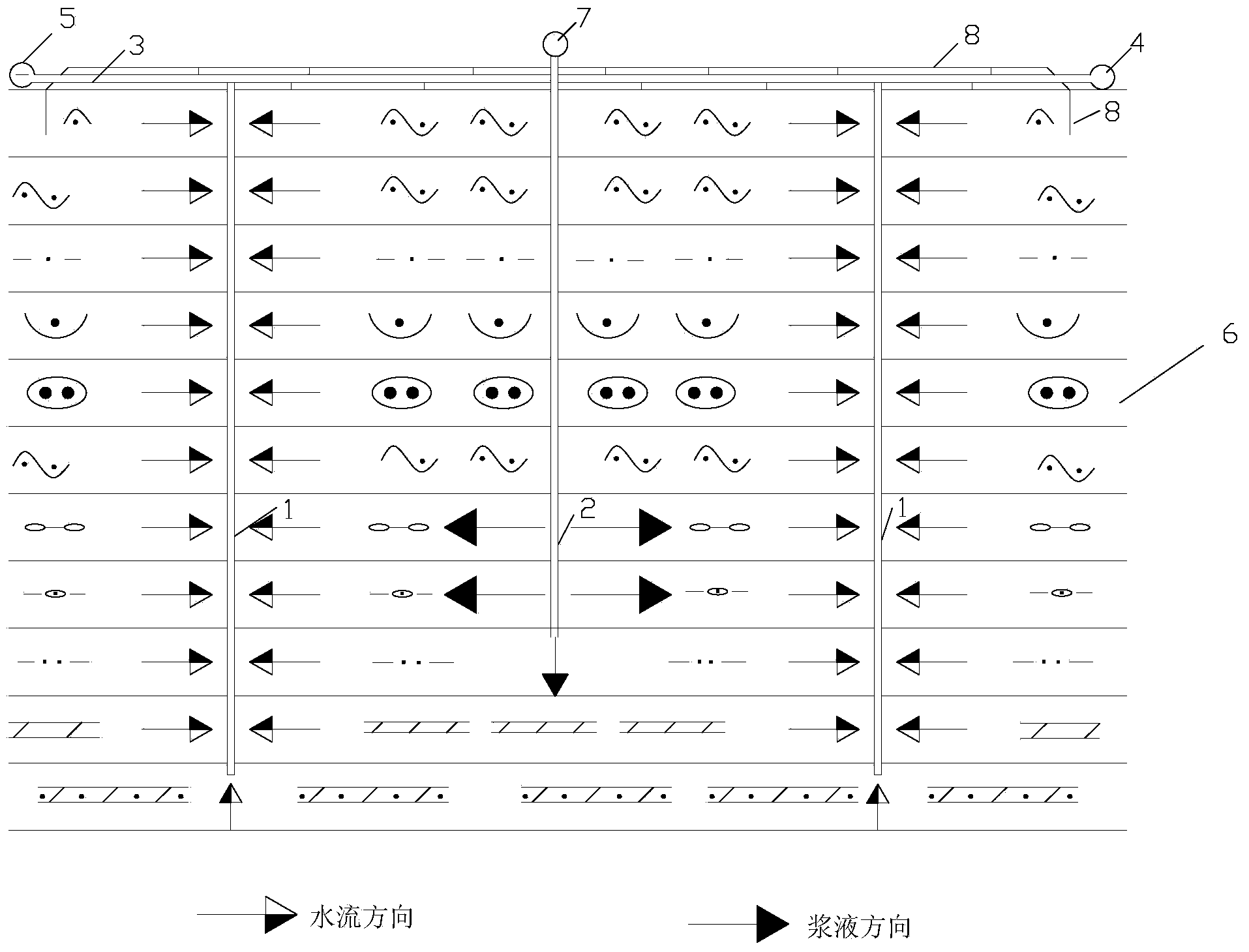
[0033] refer to Figure 1 ~ Figure 3 , a vacuum grouting process, comprising the following steps:

[0034] 1) Arrange vertical drainage boards, horizontal drainage pipes, vacuum pumps, establish a vacuum drainage system according to the ordinary vacuum preloading method, and set up a sealing film embedding ditch, etc. (as attached figure 1 ).

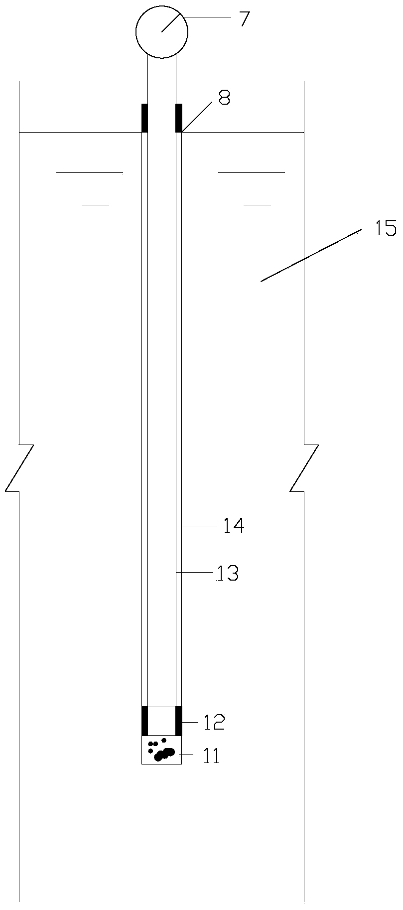
[0035] 2) Set a grouting hole at the center position equidistant from the surrounding vertical drainage board, and arrange a grouting pipe. The grouting pipe can be a plastic pipe or a steel pipe. There are several grouting holes in the middle and lower parts of the grouting pipe, and the upper part passes through the grouting branch pipe and The main pipe is connected with the grout pump.

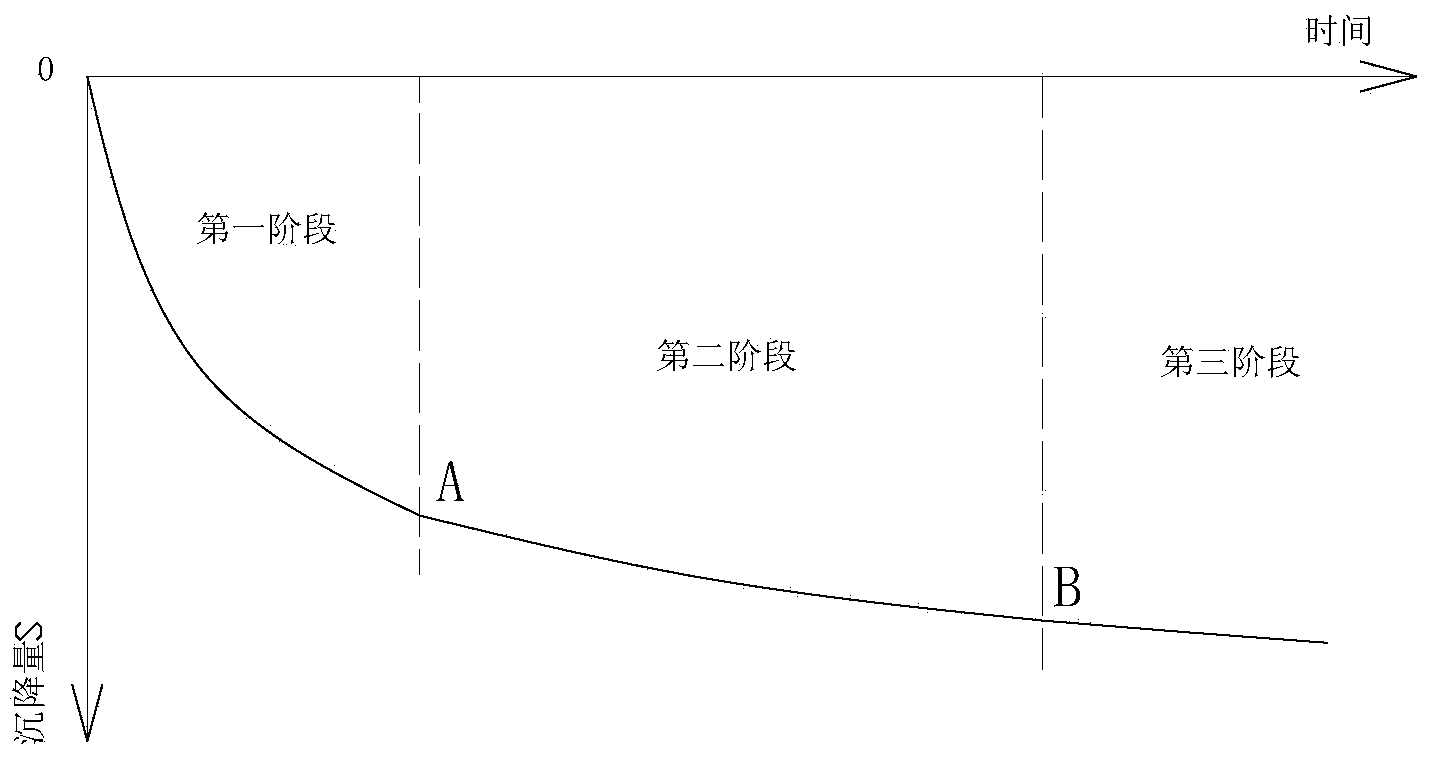
[0036] 3) Set up a vacuum pressure observation hole near the grouting hole, and establish a settlement observation point on the surface....


PUM


Abstract

The invention discloses a vacuum grouting process. The vacuum grouting process includes steps of 1), creating a vacuum drainage system according to a vacuum prepressing method; 2), forming grouting holes in center positions with equal distances to peripheral vertical drainage plates and arranging grouting pipes; 3), forming vacuum pressure observation holes in positions close to the grouting holes and setting settlement observation points on ground surfaces; 4), laying sealing films; 5), starting vacuum pumps to pump formation water and gas, observing vacuum pressures of various positions in formations and ground surface settlement, and drawing vacuum pressure changing curves of depths of the various formations and ground surface settlement curves; 6), determining first grouting time; 7), continuing to perform vacuum pumping, stopping the vacuum pumps and tracking and observing change of the ground surface settlement and change of the vacuum pressures; 8), restarting machines to perform vacuum pumping; 9), determining re-grouting time; 10), repeating the steps 7), 8) and 9) until grout can no longer be grouted into the formations or requirements on designed grouting quantities are met. The vacuum grouting process has the advantages that factors due to post-construction softening can be eliminated, and vacuum grouting soft-soil foundation treating effects and the vacuum grouting soft-soil foundation treating efficiency can be improved.

Description

technical field [0001] The invention relates to a grouting process, in particular to a vacuum grouting process, which is applied to fields such as land reclamation or soft foundation and rock soil reinforcement and treatment. Background technique [0002] Tidal flat reclamation is currently the main means of obtaining land resources from the sea in the southeast coastal provinces of my country and even the coastal countries of the world. With the continuous increase of demand for land resources in my country's coastal opening and construction, the scale of tidal reclamation is expanding day by day. Due to the large water content of the newly reclamated land, fine soil particles, strong fluidity, mostly muddy clay, and poor engineering properties, manual methods must be adopted to meet the needs of engineering construction after processing at a relatively fast speed. At present, there are many methods to improve the bearing capacity of this kind of tidal flat reclamation soft...

Claims


Application Information

Patent Timeline
IPC IPC(8): E02D3/12E02D3/10E02D1/00
Inventor 杨俊杰俞元洪吴赟干焕军王攀铭
Owner 浙江工业大学工程设计集团有限公司
Why Eureka
Try Eureka