Movable reaction equipment for shield launching shaft

A technology of counterforce equipment and originating shafts, which is applied in mining equipment, earthwork drilling, tunnels, etc., and can solve the problems of high steel pipe diameter and welding requirements, increased construction cost, construction difficulty, and increased construction cost. Problems such as the construction period, to achieve the effect of low pipe diameter requirements, shortened construction period, and low construction risk

Inactive Publication Date: 2014-09-10
CHINA RAILWAY SOUTH INVESTMENT GRP CO LTD +1
View PDF6 Cites 13 Cited by
  • Summary
  • Abstract
  • Description
  • Claims
  • Application Information

AI Technical Summary

Problems solved by technology

[0005] The above shield tunneling construction method in the vertical shaft has the following disadvantages: (1), a certain number of negative ring segments need to be manufactured, hoisted in and installed, and after the construction is completed, the negative ring segments need to be dismantled and hoisted out of the initial shaft; Outside the well, the construction cost is high, the process is many, the risk is high, and the construction period is increased
At the same time, the assembly operation of the negative ring segment also requires a relatively large origin shaft clearance, which also increases the construction cost and construction period
(2) The stressed steel pipes in the supporting part of the fixed reaction frame need to be welded and dismantled, which is cumbersome to operate and increases the construction cost and construction period
(3) The oblique support method of the reaction frame requires greater support force, and requires high pipe diameter and welding requirements for the stressed steel pipe, which also increases the construction cost and construction difficulty

Method used


Image

  • Movable reaction equipment for shield launching shaft
  • Movable reaction equipment for shield launching shaft
  • Movable reaction equipment for shield launching shaft

Examples


Embodiment Construction

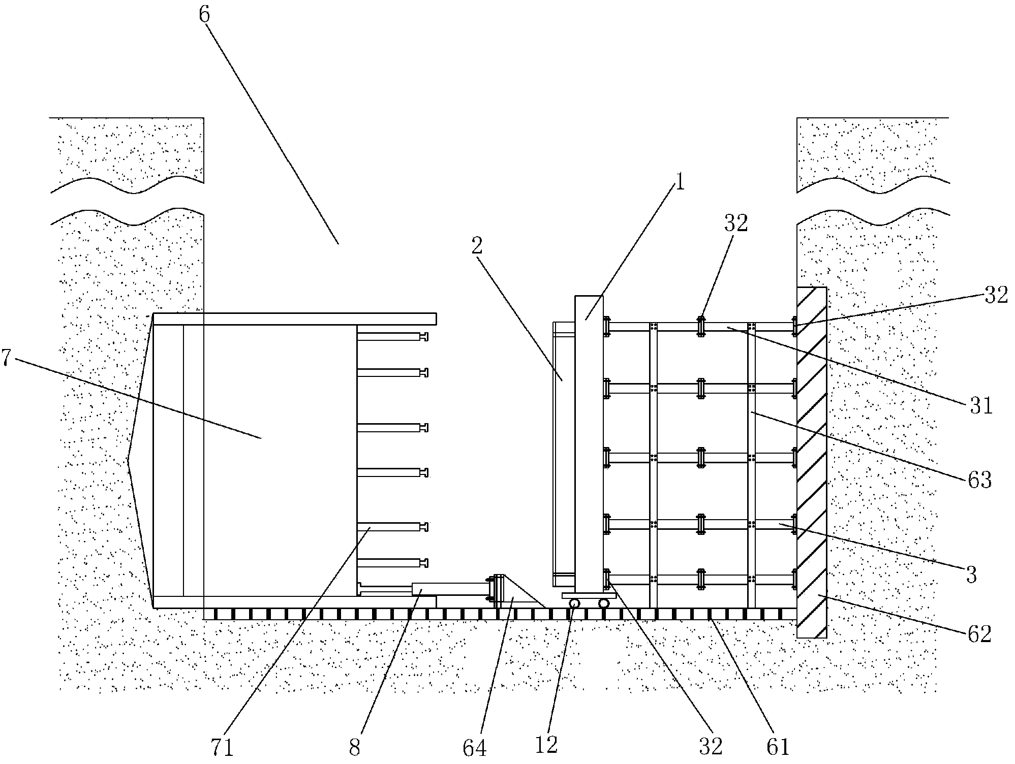
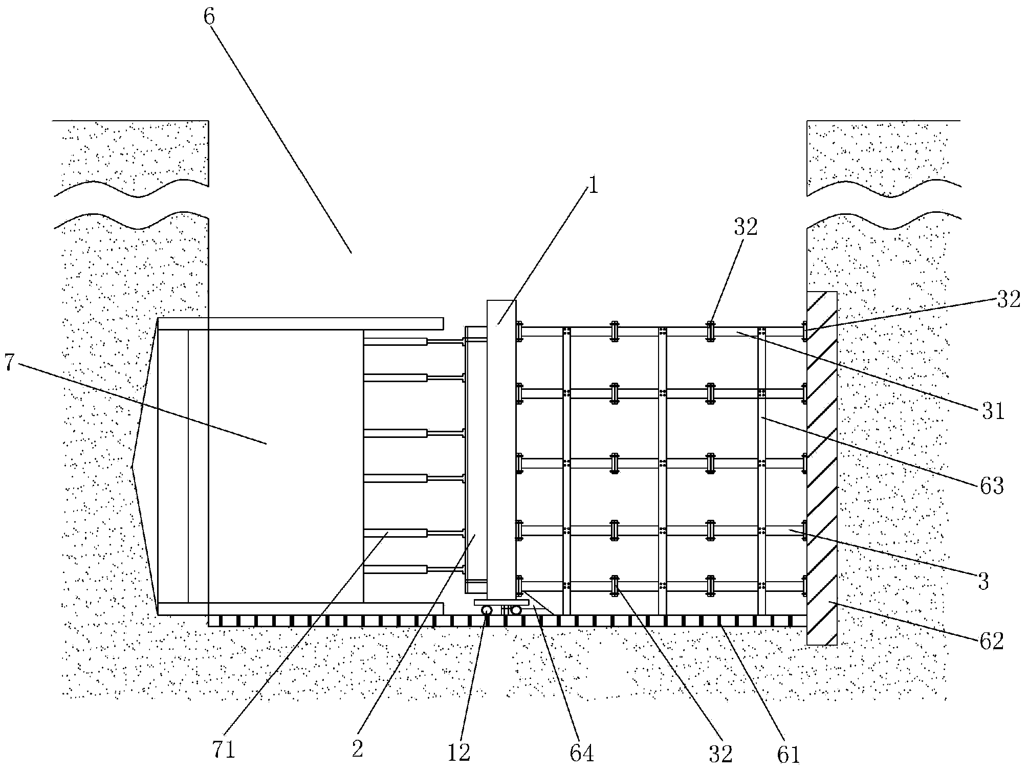
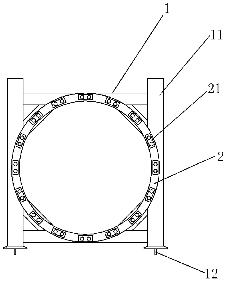
[0034] Figure 1-3 It is shown that a specific embodiment of the present invention is a movable counter force device for a shield launching shaft. On the track 61 of the bracket, the reference steel ring 2 welded to the front of the main beam 1 is characterized in that: the back of the main beam 1 is connected to the flange 32 at the front end of the horizontal support pipe 3, and the rear end of the horizontal support pipe 3 The flange 32 is close to the push-back wall 62 of the shield tunneling shaft, and the horizontal support pipe 3 is a single steel pipe 31 or more than two steel pipes 31 connected by the flange 32. The steel pipe 31 The length of the length is less than the stroke of the jack 71 of the shield machine 7;

[0035] The horizontal support pipe 3 of this example is 32-12. The steamboat 12 matching the track 61 of the starting bracket is installed at the lower end of the column 11 . The front side of the reference steel ring 2 is provided with a jack groove...


PUM


Abstract

Movable reaction equipment for a shield launching shaft comprises a girder provided with a rectangular frame, wherein the girder is perpendicularly placed on a track of a launching bracket in the shield launching shaft, and the front side of the girder is connected with a reference steel ring through welding, the back side of the girder is connected with a flange at the front end of a horizontal support tube, a flange at the back end of the horizontal support tube is closely attached to a pushing back wall of the shield launching shaft, the horizontal support tube is formed by flanged connection of one section of steel tube or at least two sections of steel tubes, and the length of each steel tube is smaller than the travel of a shield machine jack; and the front side of an embedded support piece on a bottom plate of the shield launching shaft is in threaded connection with the tail of an anti-reverse jack. The equipment is low in construction cost, simple and convenient to construct, high in construction efficiency, short in construction period and low in risk when being used for performing launching construction of the shield launching shaft.

Description

technical field [0001] The invention relates to a movable counterforce device in a shield launching shaft Background technique [0002] As an advanced tunnel construction method, "shield tunneling method" has the advantages of high degree of mechanical automation, fast construction speed, small ground disturbance, no interference with road traffic, and small impact on the surface environment. At present, it has been recognized in the field of tunnel engineering in my country Widely used, the proportion of shield tunnels in my country's transportation field will increase in the future. [0003] The first work to be carried out in the construction of a tunnel using the shield method is the initial construction of the shield machine. If the initial construction of the shield machine is not carried out in the station, it is usually necessary to construct a shaft for the initial launch of the shield machine, and then hoist the shield machine into it. The originating construction ...

Claims


Application Information

Patent Timeline
Patent Type & Authority Applications(China)
IPC IPC(8): E21D9/06
Inventor 陈寿根周泽林张国亮刘继强王太平宁锐韩雪峰张恒
Owner CHINA RAILWAY SOUTH INVESTMENT GRP CO LTD
Why Eureka
Try Eureka