Inflow Chamber For Catalytic Converter Of Emission Control System

An exhaust gas purification and catalytic converter technology, which is applied in gas chambers, exhaust gas treatment, exhaust devices, etc., can solve the problems of unsatisfactory mixing of the exhaust gas to be purified and the reducing agent, and achieve good orientation and homogeneity. the effect of

Active Publication Date: 2014-09-10
PUREM GMBH
View PDF7 Cites 11 Cited by
  • Summary
  • Abstract
  • Description
  • Claims
  • Application Information

AI Technical Summary

Problems solved by technology

[0007] It has been found that the mixing of the exhaust gas to be purified with the reducing agent in existing systems is unsatisfactory

Method used


Image

  • Inflow Chamber For Catalytic Converter Of Emission Control System
  • Inflow Chamber For Catalytic Converter Of Emission Control System
  • Inflow Chamber For Catalytic Converter Of Emission Control System

Examples


Embodiment Construction

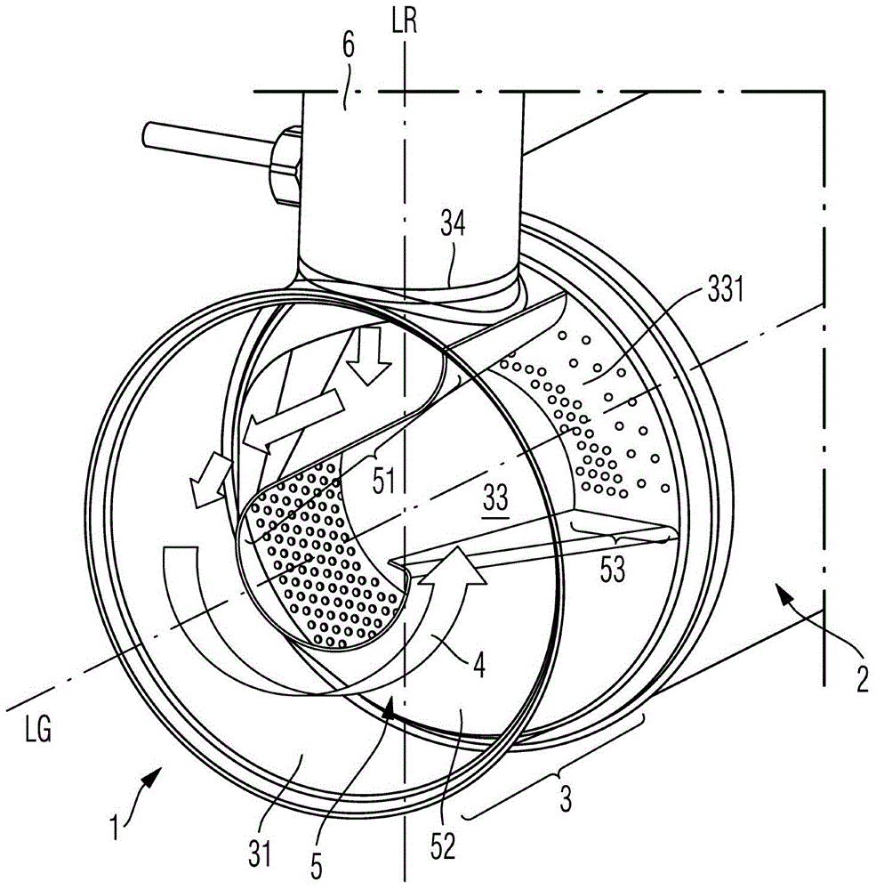
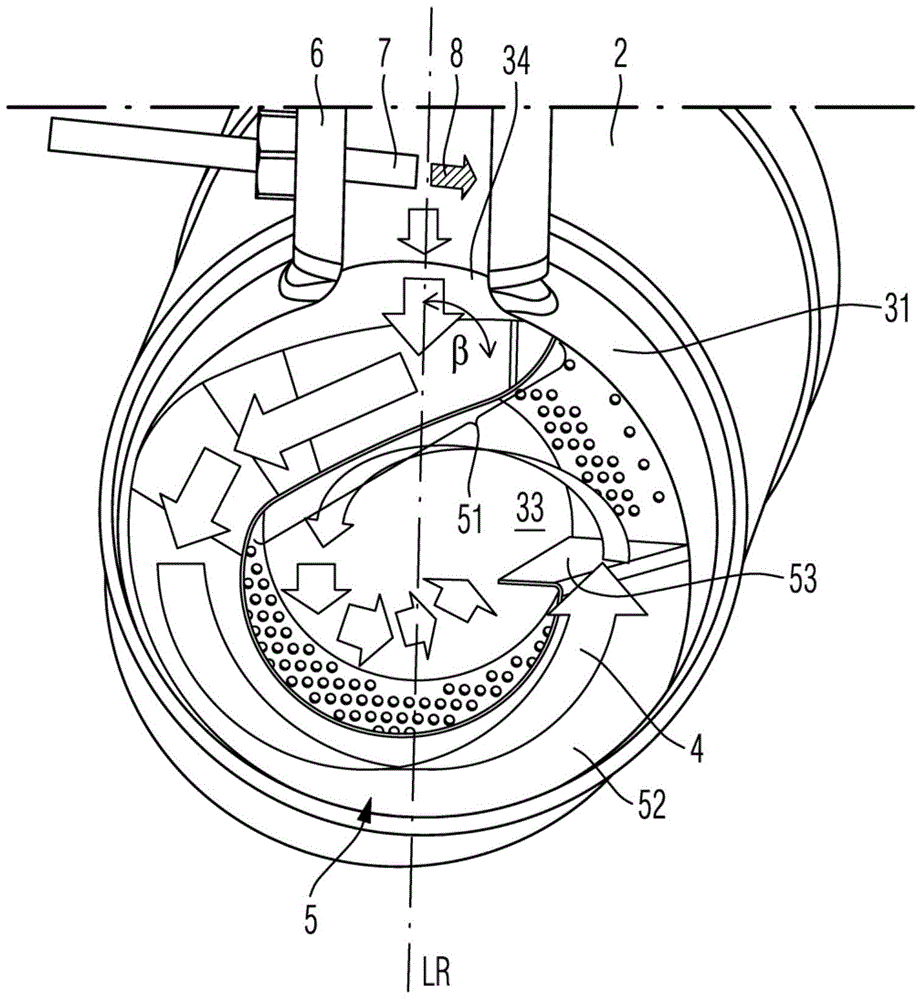
[0063] Refer below Figures 1 to 6 An embodiment of an inflow chamber 1 for an exhaust gas catalytic converter 2 is described, which can be used, for example, in Figure 7 In the motor vehicle exhaust purification system 9 shown in.

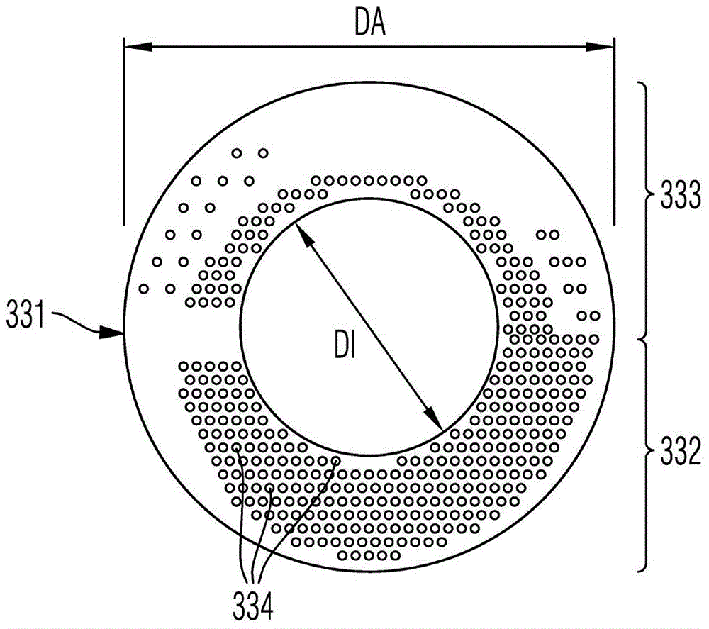
[0064] The inflow chamber 1 has a substantially cylindrical housing 3 with a peripheral surface 31 and two end surfaces 32 , 33 . exist figure 1The peripheral surface 31 facing the viewer and not shown in the middle and the first end surface 32 are made of stainless steel and are welded to each other in a gas-tight manner. In the embodiment shown, the first end face 32 is a covering cap which is also gas-tight like the peripheral face 31 itself of the cylindrical housing 3 . The second end face 33 , which is spaced apart from the first end face 32 along the longitudinal axis LG of the cylindrical housing 3 , has, in the embodiment shown, a ring 331 made of stainless steel which is likewise gas-tight on its outer edge. The ground is welded tog...


PUM

PropertyMeasurementUnit
diameteraaaaaaaaaa
diameteraaaaaaaaaa
lengthaaaaaaaaaa

Abstract

The invention relates to an inflow room (1) for an exhaust gas catalytic converter (2). The inflow room (1) comprises a cylindrical shell (3) and a guide plate (5). The cylindrical shell (3) is provided with peripheral surface (31) and two end surfaces (32, 33). The peripheral surface (31) and the first end surface (32) are made of a material through which exhaust gas cannot pass. The second end face (33) at least can be partially passed through by the exhaust. The peripheral surface (31) is provided with an entering port (34) doped with a reducing agent (8) of exhaust gas (4). The guide plate is made of a material through which exhaust gas (4) cannot pass. The guide plate (5) extends along the transverse direction from the second end surface (33) of the shell (3) to the first end surface (32), and has a tapered section (52) along the lengthways, wherein the guide plate forms the outer surface facing the circumferential surface of a truncated cone of the first end surface (32) of the cylindrical shell (3), and the conical section extends in circumferential direction of the cylindrical shell (3) at least 90 degrees, in particular at least 135 degrees, more especially more than 180 degrees.

Description

technical field [0001] The invention relates to an exhaust gas purification system for a motor vehicle, in which a liquid reducing agent is used for purification of the exhaust gas. More precisely, the invention relates to an inflow chamber of an SCR catalyst / catalytic converter (SCR=selective catalytic reduction) for an exhaust gas purification system. Such an inflow chamber is sometimes called a mixing chamber. Background technique [0002] Nitrogen oxides NO are commonly found in exhaust gases from combustion plants, waste incineration plants, gas turbines, industrial equipment and engines x . Nitrogen oxides occur during the thermal utilization of solid, gaseous and liquid natural and fossil fuels such as coal, gas, oil and wood. Nitrogen oxides are contained in particular in the exhaust gases of internal combustion engines of motor vehicles and commercial vehicles. The proportion of nitrogen oxides in the exhaust gas of internal combustion engines operated with dies...

Claims


Application Information

Patent Timeline
Patent Type & Authority Applications(China)
IPC IPC(8): F01N3/28
CPCB01F5/0647Y02T10/24F01N2610/02F01N2470/18F01N3/2892B01F5/0065F01N2240/20B01F3/04049B01F5/0688F01N3/2066F01N2490/08F01N3/28Y02A50/20Y02T10/12B01F23/2132B01F25/103B01F25/4331B01F25/4521
Inventor K·王D·福格尔斯R·格拉赫A·舒尔茨T·沃尔夫
Owner PUREM GMBH
Why Eureka
Try Eureka