Machine vision based LED detection device and detection method thereof

A machine vision and detection device technology, applied in the direction of testing optical performance, etc., can solve the problems of not suitable for mass application in production lines, not supporting simultaneous detection of multiple LEDs, low detection efficiency, etc., achieving low cost, improved stability, and cost savings Effect

Active Publication Date: 2014-09-10
华高科技(苏州)有限公司
View PDF5 Cites 16 Cited by
  • Summary
  • Abstract
  • Description
  • Claims
  • Application Information

AI Technical Summary

Problems solved by technology

However, the cost of using sensors for detection is high, it does not support simultaneous detection of multiple LEDs, and has disadvantages such as low detection efficiency. The method of detecting the LED conduction voltage drop is an indirect measurement method, which cannot really measure the typical characteristics of the LED, such as color, brightness, etc.

Method used


Image

  • Machine vision based LED detection device and detection method thereof
  • Machine vision based LED detection device and detection method thereof
  • Machine vision based LED detection device and detection method thereof

Examples


Embodiment 1

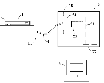
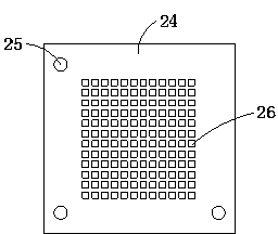
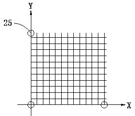
[0039] Such as Figure 1 to Figure 3 Shown is an embodiment of the machine vision-based LED inspection device of the present invention. Such as figure 1 , figure 2 As shown, the LED detection device includes a carrier board fixture 1 for placing the LED to be tested, a dark box 2, and an industrial computer 3. The dark box 2 is provided with an industrial camera 21 connected to the industrial computer 3. The industrial camera 21 is arranged on the dark box 2. The camera bracket 22 inside is fixedly supported, the industrial camera 21 is provided with a fixed-focus lens 23, and the camera obscura 2 is also provided with a light-condensing plate 24 arranged at the front end of the fixed-focus lens 23, and three positioning lights with different colors are arranged on the plane of the light-condensing plate 24. 25 , a through hole 26 is set in the plane of the coordinate system formed by the positioning light 25 , and the carrier fixture 1 is connected to the through hole 26 t...

Embodiment 2

[0045] The present invention is the embodiment that adopts the detection method of above-mentioned LED detection device based on machine vision, comprises the following steps:

[0046] S1. The LED to be tested lights up and emits light, and the LED light is transmitted to the light collecting plate in the dark box through the conductive fiber;

[0047] S2. The industrial camera collects the original image on the condensing plate and transmits it to the industrial computer through the Gigabit network card;

[0048] S3. The industrial computer preprocesses the collected original image, and first recognizes three color positioning lights with red, green and blue colors respectively;

[0049] S4. The industrial computer calculates the region of interest after obtaining the positioning light, and maps this area to the original image, and further recognizes the position coordinates of the three colored positioning lights through the principle of three primary colors; after the posit...


PUM


Abstract

The invention relates to the technical field of machine vision, in particular to a machine vision based LED detection device and a detection method thereof. The LED detection device comprises a carrier plate clamp, a camera obscura and an industrial personal computer, an industrial camera connected with the industrial personal computer is arranged in the camera obscura, a prime lens is arranged on the industrial camera, a condensation plate disposed at the front end of the prime lens is further arranged in the camera obscura, at least two positioning lamps are arranged on a plane of the condensation plate, through holes are formed in a coordinate system plane formed by the positioning plates, and the carrier plate clamp is connected with the through holes through a conduction fiber. The machine vision based LED detection device can detect LEDs quickly, efficiently and stably with low cost, and is applicable to any application environment needing to detect a large quantity of printed circuit board LEDs; the detection method can quickly and efficiently complete detection of dozens of LEDs, and is simple, convenient and rapid to operate.

Description

technical field [0001] The invention relates to the technical field of machine vision, and more particularly, to a machine vision-based LED detection device and a detection method thereof. Background technique [0002] Machine vision, as the name implies, is to enable the machine to have human-like visual functions, so as to realize various detection, judgment, identification, measurement and other functions. A machine vision system is generally composed of a camera, an image acquisition card, a computer, and a light source. Its working principle is: under certain lighting conditions, use the camera to collect the captured target image of the 3D scene into the computer to form an original image; then, use the image The processing technology preprocesses the original image to improve the image quality, divides the image, extracts the characteristic elements, and constitutes the description of the image; finally, adopts the pattern recognition technology to classify the charac...

Claims


Application Information

Patent Timeline
Patent Type & Authority Applications(China)
IPC IPC(8): G01M11/02
Inventor 张伟军
Owner 华高科技(苏州)有限公司
Why Eureka
Try Eureka