
Differential information transmitting method of satellite navigation satellite navigation receiver and corresponding receiver

A technology of differential information and satellite navigation, applied in satellite radio beacon positioning systems, measuring devices, instruments, etc., can solve problems such as increased power consumption, increased user costs, and increased costs

Active Publication Date: 2014-09-10
TECHTOTOP MICROELECTRONICS
View PDF5 Cites 24 Cited by
  • Summary
  • Abstract
  • Description
  • Claims
  • Application Information

AI Technical Summary

Problems solved by technology

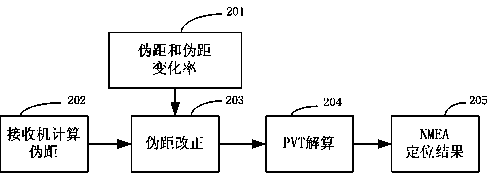
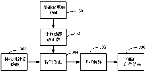
[0014] In the differential positioning system, different differential systems are based on this idea. The GNSS positioning performance is improved by enhancing the GNSS system. The receiver needs to use these enhanced services to make some supplements and adjustments in software and hardware design. The differential system The improvement of receiver processing capability and processing speed increases its cost and power consumption. At the same time, the receiver needs to receive the differential information of the differential station in real time, resulting in a large data flow and increasing user costs.

Method used


Image

  • Differential information transmitting method of satellite navigation satellite navigation receiver and corresponding receiver
  • Differential information transmitting method of satellite navigation satellite navigation receiver and corresponding receiver
  • Differential information transmitting method of satellite navigation satellite navigation receiver and corresponding receiver

Examples


Embodiment 1

[0048] The receiver fixedly receives the differential information of the differential station every N (1~600) seconds, corrects the pseudo-range, and no longer receives the differential information within this time period. Usually, the value of N can be dynamically configured.

Embodiment 2

[0050] The receiver calculates its own movement speed, or obtains the speed information of the receiver from the sensor, and then determines the frequency at which the receiver receives differential information through the speed of the speed. If the receiver moves faster, the frequency of receiving differential information will be accelerated. If the receiver Slower motion reduces the frequency at which the receiver receives differential information. Table 1 illustrates the relationship between the speed of the receiver and the frequency of differential information received by the receiver. It can be seen that the faster the speed, the higher the frequency received.

[0051]

[0052] Table 1 The relationship between the speed of the receiver and the frequency of the differential information received by the receiver

Embodiment 3

[0054] The receiver calculates its own position information, and then calculates the distance between the receiver and the precise coordinates of the reference station, and then determines the frequency at which the receiver receives differential information based on the distance between the receiver and the reference station. If the receiver is far away from the reference station, it will speed up The frequency at which the receiver receives differential information. If the receiver is closer to the reference station, reduce the frequency at which the receiver receives differential information. Table 2 illustrates the relationship between the distance between the receiver and the reference station. It can be seen that the farther the distance between the receiver and the reference station, the higher the frequency received.

[0055]

[0056] Table 2 The relationship between the distance between the receiver and the reference station and the frequency of differential informa...


PUM


Abstract

The invention discloses a differential information transmitting method of a satellite navigation satellite navigation receiver and a corresponding receiver. The differential information is used for improving the location or time service precision of the receiver. The method comprises the steps: a step of acquiring the position, acquiring the current position information of the receiver; a step of calculating the distance: calculating the distance between the current position information and a differential reference station; a step of setting transmission frequency: receiving the transmission frequency of the differential information of the receiver according to the distance, and acquiring the differential information according to the transmission frequency. By adopting the technical way, the broadcasting frequency of the differential information can be reduced by the timeliness of GNSS (Global Navigation Satellite System) differential information, the transmission flow of the differential information can be reduced, the communication cost can be reduced, and the communication pressure of a server in a reference station can be greatly reduced.

Description

technical field [0001] The invention relates to a differential information transmission method of a satellite navigation receiver and a corresponding receiver. Background technique [0002] GNSS (Global Navigation Satellite System) is a general term for all navigation satellite systems worldwide, including GPS (Global Positioning System, US Global Positioning System), GLONASS (Russian Glonass Navigation Satellite System), Galileo (European Galileo Navigation Satellite System), BDS (China Beidou Navigation Satellite System), etc., all of the above navigation satellite systems are designed to provide users with satellite navigation and positioning services around the clock. [0003] At present, the most common positioning mode of satellite receivers is: the ground receiving end receives satellite signals broadcast by navigation satellites, demodulates and collects enough data information to calculate the current position information of the ground receiving end, and generally n...

Claims


Application Information

Patent Timeline
IPC IPC(8): G01S19/24
CPCG01S19/07
Inventor 刘丽宁孙功宪
Owner TECHTOTOP MICROELECTRONICS
Learn More