Control circuit of gate driving circuit, working method and display device
A gate drive circuit and control circuit technology, applied in electrical components, static indicators, generating electrical pulses, etc., can solve the problems of high power consumption of gate drive circuits and shortened life of thin film transistors, etc.
- Summary
- Abstract
- Description
- Claims
- Application Information
AI Technical Summary
Problems solved by technology
Method used
Image
Examples
Embodiment 1
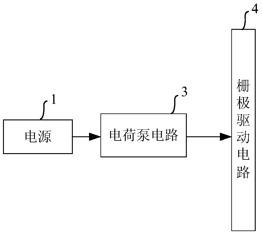
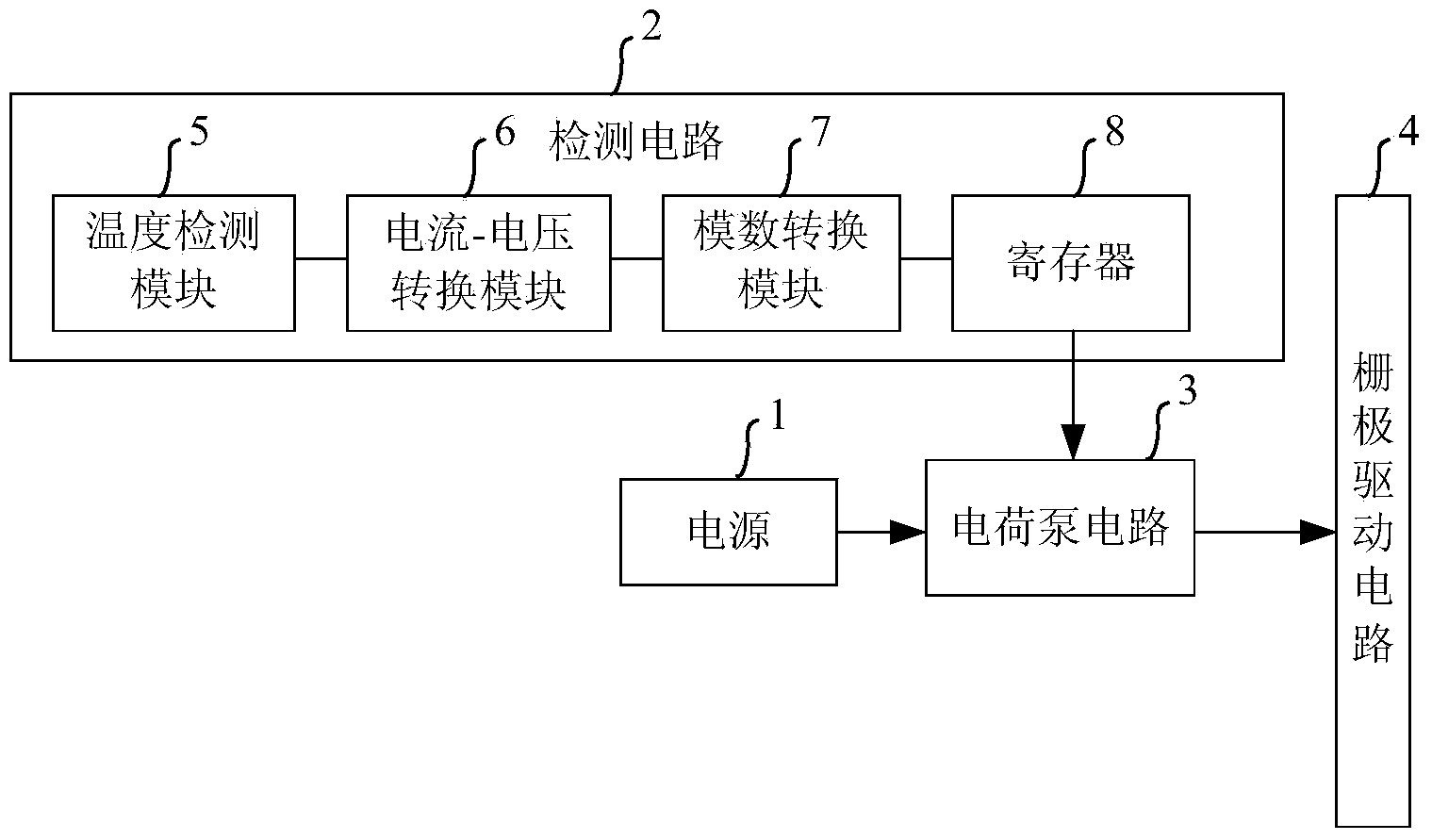
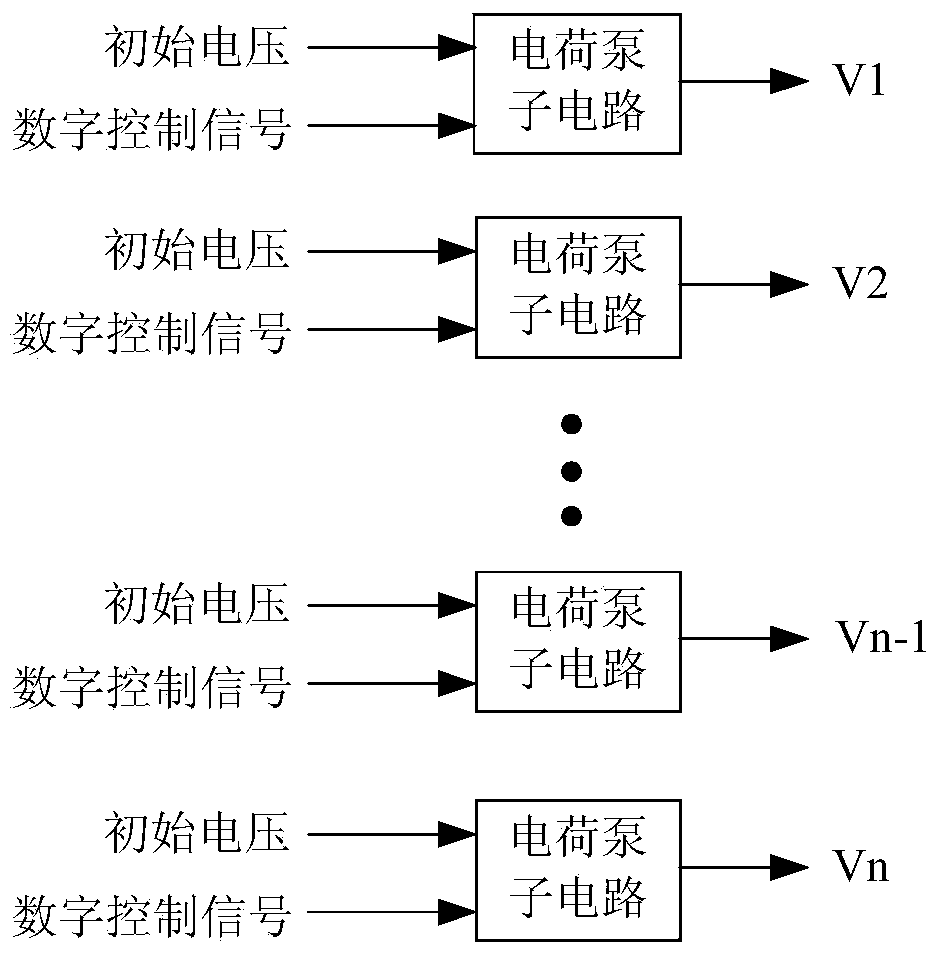
[0045] figure 2 A schematic structural diagram of the control circuit of the gate drive circuit provided in Embodiment 1 of the present invention, as shown in figure 2 As shown, the control circuit includes: a power supply 1, a detection circuit 2, and a charge pump circuit 3, wherein the detection circuit 2 generates a corresponding digital control signal according to the ambient temperature of the gate drive circuit 4, and the power supply 1 is used to provide the charge pump circuit 3 with The initial voltage, the charge pump circuit 3 is used to adjust the initial voltage according to the digital control signal to generate a driving voltage, and output the driving voltage to the gate driving circuit 4 .
[0046]The technical solution in the present invention senses the current ambient temperature of the gate drive circuit 4 through the detection circuit 2, and generates a digital control signal corresponding to the ambient temperature according to the current ambient tem...
Embodiment 2
[0069] Embodiment 2 of the present invention provides a display device. The display device includes: a control circuit of a gate drive circuit. The control circuit of the gate drive circuit adopts the control circuit of the gate drive circuit provided in Embodiment 1 above. Specifically, Refer to the description in the first embodiment above, and details are not repeated here.
[0070] Embodiment 2 of the present invention provides a display device. The display device includes: a control circuit of a gate drive circuit, and the control circuit of the gate drive circuit includes: a detection circuit, a power supply, and a charge pump circuit. The technical solution of the present invention adopts The detection circuit generates a corresponding digital control signal according to the ambient temperature of the gate drive circuit, and the charge pump circuit adjusts the initial voltage according to the digital control signal to generate the driving voltage VGH required to normally...
Embodiment 3
[0072] Figure 5 A flow chart of the working method of the control circuit of the gate drive circuit provided in Embodiment 3 of the present invention, as shown in Figure 5As shown, wherein, the gate drive circuit includes: a detection circuit, a power supply, and a charge pump circuit, and the working method includes:
[0073] Step 101: The detection circuit generates a digital control signal corresponding to the ambient temperature according to the ambient temperature of the gate drive circuit.
[0074] Optionally, the detection circuit includes: a temperature detection module, a current-voltage conversion module, an analog-to-digital conversion module and a register, and step 101 includes:
[0075] Step 1011: The temperature detection module generates an analog output current corresponding to the ambient temperature according to the ambient temperature of the gate drive circuit.
[0076] Wherein, the temperature detection module includes: a voltage generator and at least...
PUM
 Abstract
Description
Claims
Application Information
 - R&D
- Intellectual Property
- Life Sciences
- Materials
- Tech Scout
- Unparalleled Data Quality
- Higher Quality Content
- 60% Fewer Hallucinations
Browse by: Latest US Patents, China's latest patents, Technical Efficacy Thesaurus, Application Domain, Technology Topic, Popular Technical Reports.
© 2025 PatSnap. All rights reserved.Legal|Privacy policy|Modern Slavery Act Transparency Statement|Sitemap|About US| Contact US: help@patsnap.com


