Laser projection display device and laser drive control method

A technology of display device and laser projection, which is applied in the direction of using projection device image reproducer, static indicator, picture duplicator, etc., which can solve problems such as change and white balance change of the display screen, so as to reduce change, prevent blackening, High-quality images show the effect

Active Publication Date: 2014-09-10
HITACHI-LG DATA STORAGE
View PDF6 Cites 15 Cited by
  • Summary
  • Abstract
  • Description
  • Claims
  • Application Information

AI Technical Summary

Problems solved by technology

In small projectors using the above-mentioned semiconductor lasers, it is known that there is a problem that the light quantity and forward current characteristics of the semiconductor lasers used change due to load fluctuations and temperature, and thus the white balance of the display screen changes.

Method used


Image

  • Laser projection display device and laser drive control method
  • Laser projection display device and laser drive control method
  • Laser projection display device and laser drive control method

Examples


Embodiment 1

[0063] pass Figure 5 to Figure 13 Example 1 of the present invention will be described.

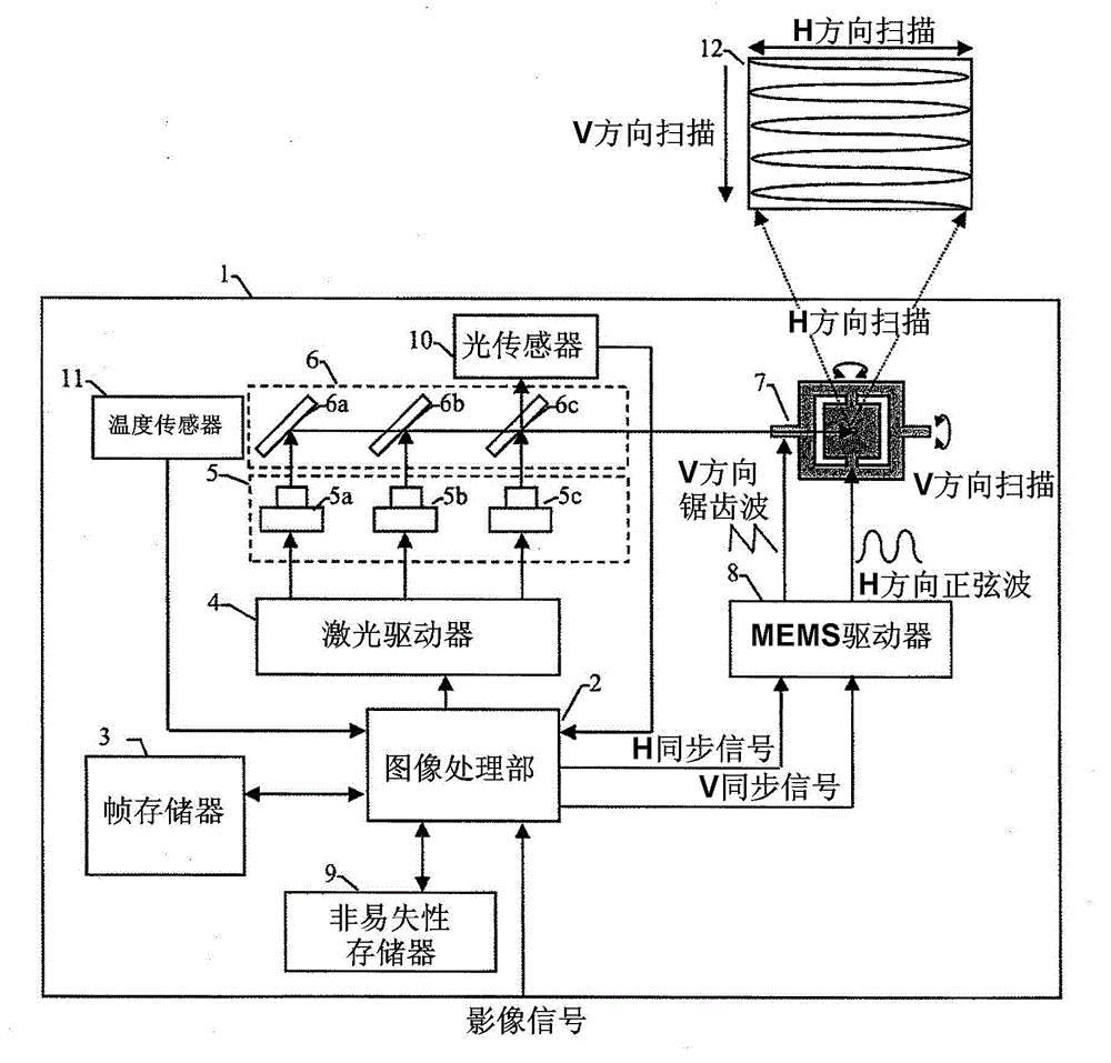
[0064] Figure 5 yes means figure 1 A diagram of the details of the internal structure of the image processing section 2 and the laser driver 4 . An image signal input from the outside of the image processing unit 2 is input to the image correcting unit 50 . The image correction unit 50 performs general image quality correction processing such as correction of image distortion due to scanning by the MEMS scanning mirror 7 and gamma adjustment of the image, and sends an image signal to the feature detection unit 51 .

[0065] The feature detection unit 51 detects image feature quantities such as APL (Average Picture Level), histogram, hue, histogram and hue of each region when the image is divided into a plurality of regions. In particular, this embodiment is useful because the APL representing the average image luminance of each color frame corresponds to the above-mentioned load on ...

Embodiment 2

[0129] In the first embodiment described above, an example in which current gain is performed based on the temperature information of the temperature sensor 11 and the ACL value of the frame has been described. In addition to this control method, it is also possible to control the current gain by increasing the light emission for current gain control with a different light emission intensity from the processing for threshold current control. In this case, the threshold current and the slope of the light intensity with respect to the image signal can be kept constant even against sudden changes in temperature and load, and the same effect as that of the first embodiment can be obtained. Furthermore, in this control method, since the temperature sensor 11 is unnecessary, cost can be reduced.

[0130]Hereinafter, the structure in which light emission for current gain control is increased is referred to as Embodiment 2 of the present invention, referring to Figure 14 ~ Figure 18...

Embodiment 3

[0174] The following describes an embodiment in which the light sensor and the temperature sensor are canceled, and the threshold current adjustment amount and the current gain value are controlled according to the feature value of the image.

[0175] In Embodiments 1 and 2 above, an example in which the state of the laser light source 5 is detected by the optical sensor 10 and the temperature sensor 11 and the threshold current and current gain are controlled is described. And it discloses a method for adjusting the threshold current and the current gain when the scene of the displayed image changes.

[0176] As described above, the main reason for the necessity of these threshold current and current gain adjustments is that the temperature rise due to the accumulation of optical conversion loss of the semiconductor laser is to such an extent that the temperature characteristics of the semiconductor laser output are affected. In the third embodiment, the estimation of the tem...


PUM


Abstract

A laser projection display device includes: a laser light source drive unit; an attribute amount detection unit for detecting the attribute amount of a picture signal; a light sensor for measuring the light amounts of the laser light sources; and a temperature sensor for measuring the temperatures of the laser light sources. The laser projection display device is configured so that the current vs. light amount output characteristics of the laser light sources with a threshold current and current gain as a parameter are corrected in accordance with the load amount of the picture signal per frame if the change of the attribute amount exceeds a predefined amount; the light sources are driven at a predefined timing of the vertical blanking interval; controls the threshold currents and current gains in accordance with the light amounts; and the threshold currents and current gains are corrected on the basis of the measured temperatures.

Description

technical field [0001] The present invention relates to a laser projection display device that displays an image by scanning a light source such as a semiconductor laser with a two-dimensional scanning mirror such as a MEMS mirror, and relates to drive control of a semiconductor laser that emits image light. Background technique [0002] Small projectors using MEMS and semiconductor laser light sources have become popular in recent years. For example, Patent Documents 1 and 2 disclose projectors that project images by scanning a biaxial MEMS mirror or scanner in horizontal and vertical directions while modulating a laser light source. In small projectors using the above-mentioned semiconductor lasers, it is known that there is a problem that the light quantity and forward current characteristics of the semiconductor lasers used change due to load fluctuations and temperature, and thus the white balance of the display screen changes. . [0003] Patent Document 2 describes a...

Claims


Application Information

Patent Timeline
Patent Type & Authority Applications(China)
IPC IPC(8): H04N9/31
CPCH04N9/3161H04N9/3182H04N9/3129G09G2320/0238G09G2360/145G09G2320/041G09G3/002G09G2360/16G09G2320/0242G09G3/025H04N9/3135G09G5/02G09G2320/0247G09G2320/103G09G3/2081G09G2320/0666
Inventor 大木佑哉瀬尾欣穗春名史雄上田寿男野中智之
Owner HITACHI-LG DATA STORAGE
Why Eureka
Try Eureka