Supercharge Your Innovation With Domain-Expert AI Agents!

Transportable reformer

A reformer, reformer tube technology, applied in the field of reformers, can solve the problems of time-consuming, delay in the completion of the factory, etc.

Inactive Publication Date: 2014-09-10
THYSSENKRUPP IND SOLUTIONS AG
View PDF4 Cites 1 Cited by
  • Summary
  • Abstract
  • Description
  • Claims
  • Application Information

AI Technical Summary

Problems solved by technology

This assembly is time consuming and requires a considerable amount of personnel and tools
Delays in completion of factories due to lack of competent personnel are common in some locations

Method used


Image

  • Transportable reformer
  • Transportable reformer

Examples


Embodiment Construction

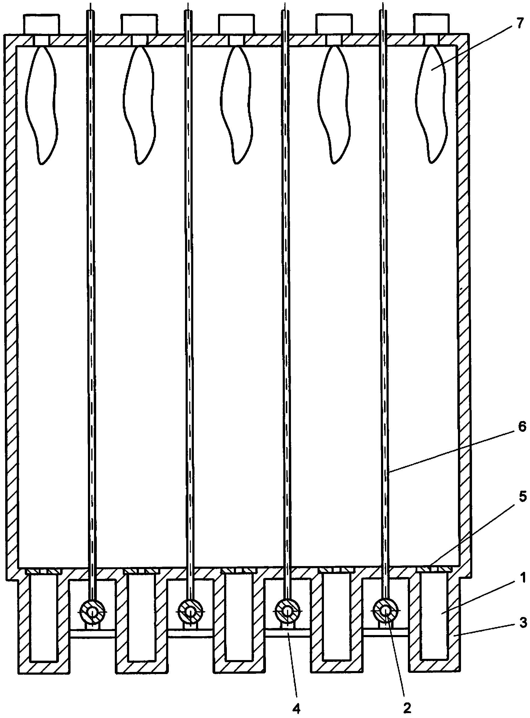
[0035] A fully assembled reformer can be shipped as a unit. The reaction chamber, which basically comprises the reformer tube system and the combustion device, is only shown here in a simplified manner.

[0036] figure 1 Shown are a plurality of flue gas channels (1) arranged in parallel in the horizontal direction below the combustion zone and manifolds (2), said flue gas channels (1) being positioned between each manifold (2). The depth of the flue gas channel can be 2m to 3m, preferably 2.5m, the width of the flue gas channel is 0.5m to 0.8m, and the refractory lining (3) of the flue gas channel (1) is about 0.2m to 0.35m. The diameter of the manifold (2) including the refractory lining is 0.5 to 0.66 meters.

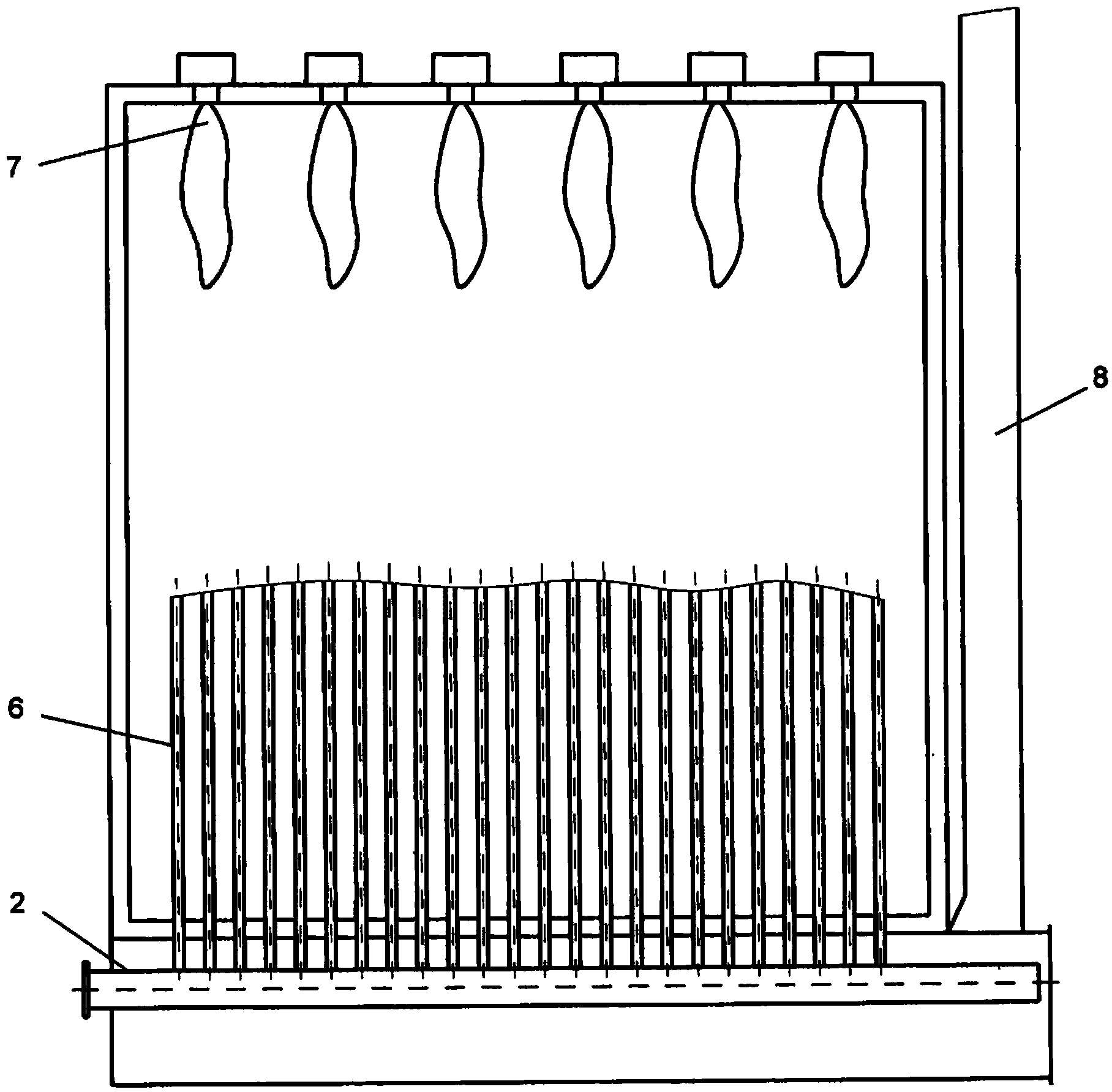
[0037] In addition to the burner (7), process gas pipe (6) and manifold (2), figure 2 Also shown is the warm air stack (8) enabling a constant supply of fresh air between the manifolds.


PUM


Abstract

The invention relates to a transportable reformer for the catalytic primary reformation of hydrocarbons with water vapour under elevated pressure, having a reforming tube system and a firing chamber. As a reaction chamber, the reforming tube system comprises a plurality of vertical tubes arranged in rows and suitable for filling with catalysts, and devices for feeding reforming hydrocarbons and water vapour to the reaction chamber, and has in the upper region of the firing chamber a plurality of firing devices arranged parallel to one another. The firing devices arranged in parallel to one another are each arranged between the reforming tubes and comprise: a plurality of burners arranged in series, the burners being able to generate flames directed substantially upwards and suitable for heating the reforming tubes; header pipes for discharging reformed synthesis gases from the reaction chamber, the header pipes lying outside of the reaction chamber; and flue gas tunnels for discharging the flue gas produced in the firing chamber. A plurality of flue gas tunnels horizontally parallel to one another are arranged below the firing chamber, each of the flue gas tunnels are arranged between the header pipes, the flue gas tunnel and the firing chamber are firmly connected to one another, and the header pipes are connected to the flue gas tunnel in such a way that they are connected to the rest of the reformer and the finally assembled reformer is executed as the transportable reformer.

Description

technical field [0001] The present invention relates to a transportable reformer for the catalytic reforming of hydrocarbons using steam at elevated pressure to produce synthesis gas. This synthesis gas can be used, for example, to produce ammonia, hydrogen and methanol, and the reformer is designed to be transportable. Background technique [0002] Reactors for the catalytic reforming of hydrocarbons using steam have been known for a long time in numerous examples. For large-scale plants, a class of installations has established itself, in which top-firing chamber furnaces with vertically arranged reaction tubes, or rather reformer tubes, are used. Here, the reformer tubes are arranged in rows. Feedstock flows from top to bottom through reformer tubes filled with catalyst, and in doing so, a so-called reforming process is carried out. [0003] The gas outlet temperature is usually above 850°C. The process gases leaving the reforming tubes are collected in manifolds loca...

Claims


Application Information

Patent Timeline
IPC IPC(8): C01B3/38B01J8/06
CPCC01B2203/0816C01B3/384B01J2219/0002B01J8/062C01B2203/0233Y02E60/32
Inventor 奥利弗·迈斯纳法尔克·拜尔
Owner THYSSENKRUPP IND SOLUTIONS AG
Features
  • R&D
  • Intellectual Property
  • Life Sciences
  • Materials
  • Tech Scout
  • Unparalleled Data Quality
  • Higher Quality Content
  • 60% Fewer Hallucinations
Learn More