Gear type rotary engine

A rotary engine and gear type technology, applied in combustion engines, machines/engines, internal combustion piston engines, etc., can solve the problems of high weight, complex engine structure, small effective arm, etc., and achieve high energy conversion efficiency, easy and fast. Start and stop, reduce the effect of eccentric vibration

Inactive Publication Date: 2014-09-17
曹瑞
View PDF7 Cites 6 Cited by
  • Summary
  • Abstract
  • Description
  • Claims
  • Application Information

AI Technical Summary

Problems solved by technology

[0004] (1) The structure of the engine is complex, including reciprocating components such as pistons, crankshafts, and connecting rods. Its own weight is large, so it consumes a lot of energy;
[0005] (2) When the crankshaft and connecting rod in the engine perform power output, the effective arm of the component piston is very small when it is close to the upper and lower dead centers, so the energy conversion rate is low;
[0006] (3) The piston in the engine mainly performs reciprocating motion, which causes relatively large vibration and noise
[0008] (1) The vibration noise generated by the eccentric rotation of the triangular rotor inside the engine is relatively large;
[0009] (2) The shape of the combustion chamber of the rotary engine is not conducive to complete combustion, and the internal flame propagation path is long, which makes the consumption of fuel and engine oil relatively large;
[0010] (3) The processing and manufacturing technology of the rotary engine is high, the cost is relatively expensive, and it is difficult to promote

Method used


Image

  • Gear type rotary engine
  • Gear type rotary engine
  • Gear type rotary engine

Examples


Embodiment Construction

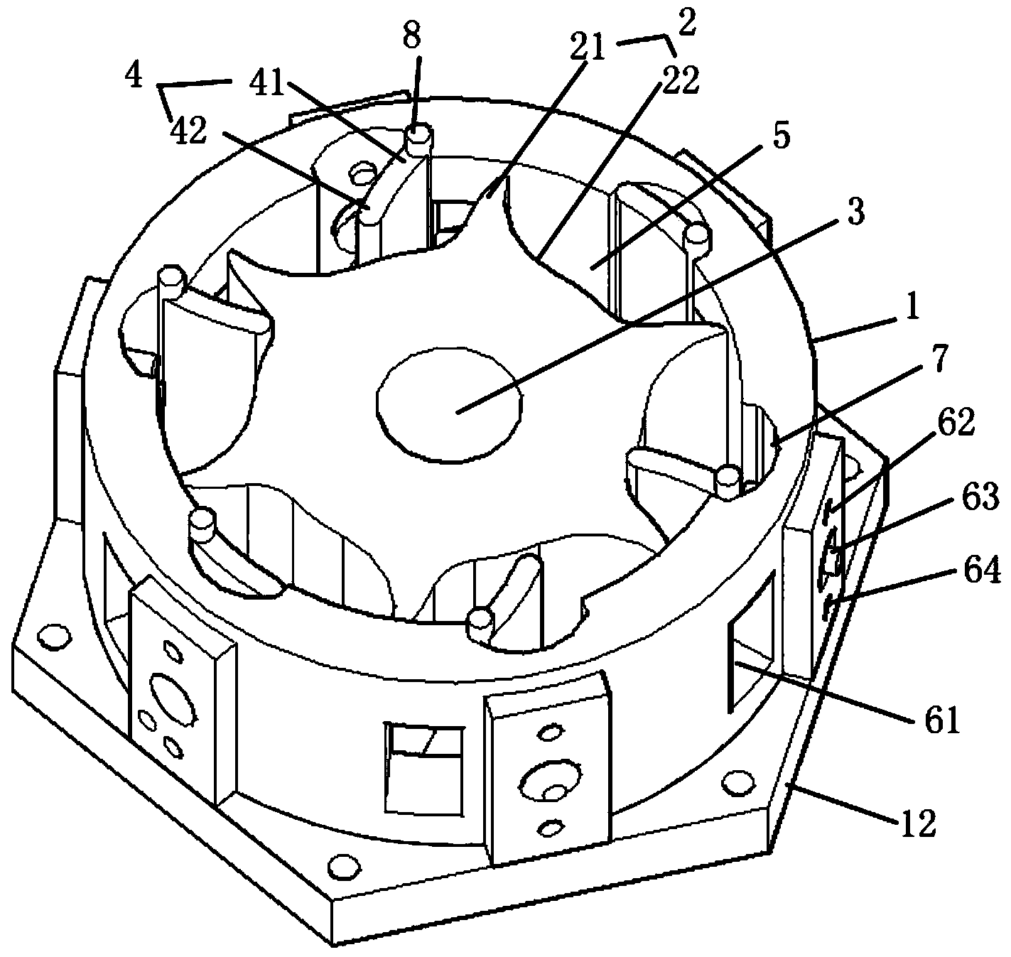
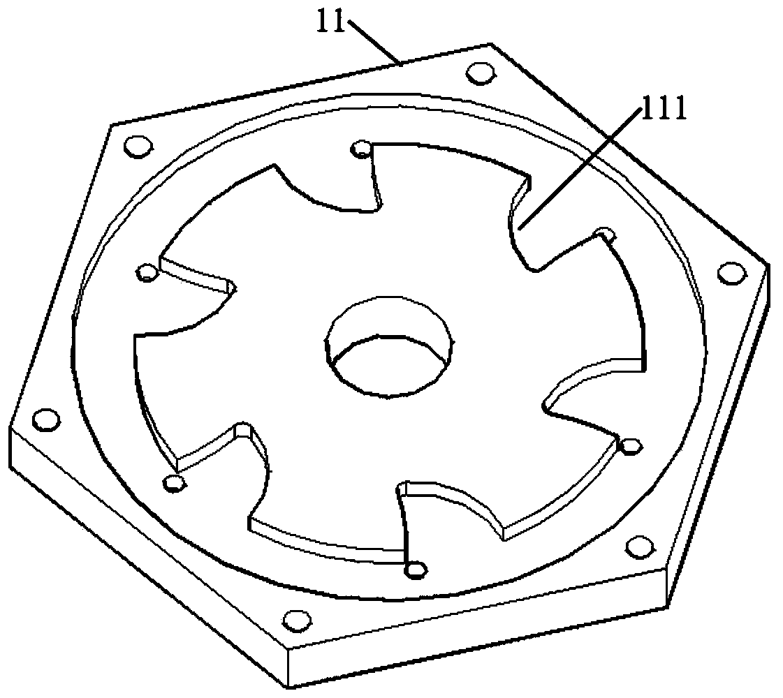
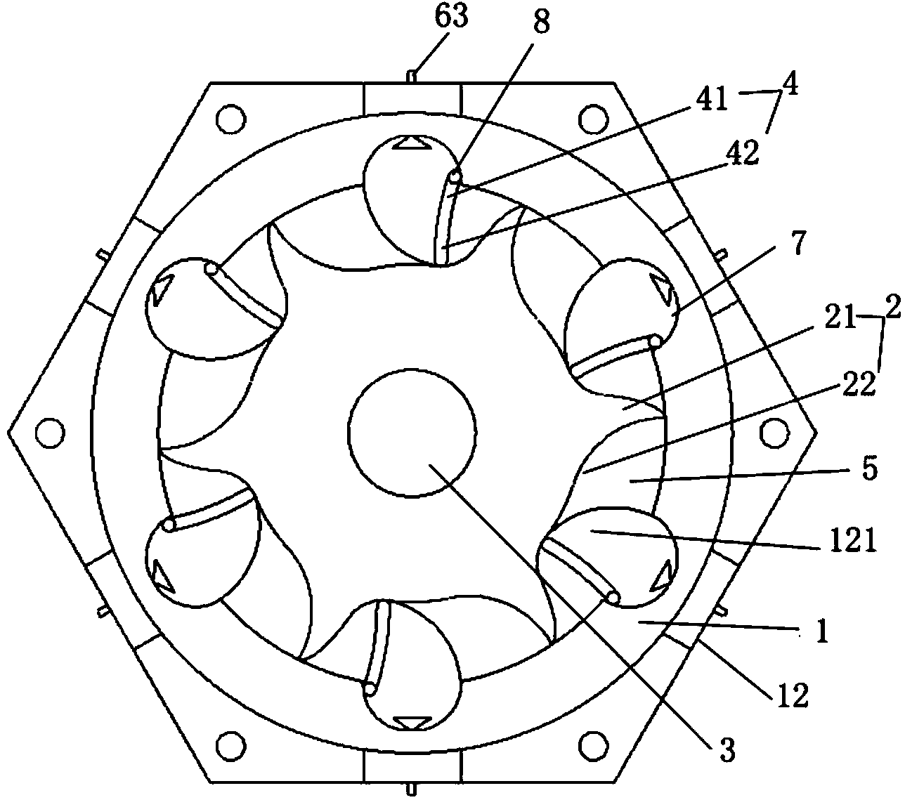
[0039] The invention provides a geared rotor 2 engine, which belongs to the internal combustion engine, and its material is preferably cast iron or cast aluminum. Such as Figure 1-2 As shown, in terms of structure, the engine mainly includes a stator 1, a rotor 2, an output shaft 3 and a dial 4; wherein, the external shape of the above-mentioned stator 1 is, for example but not limited to, a regular hexagonal column or a cylinder, etc., in the stator 1 There is a cylindrical cavity inside for accommodating the rotor 2 and the output shaft 3. The upper and lower ends of the stator 1 are also provided with an upper end cover 11 and a lower end cover 12 respectively. The screw is tightened so that the cavity inside the stator 1 forms a closed cavity.

[0040] The above-mentioned rotor 2 is a geared rotor, and the rotor 2 includes gear teeth 21 and tooth slots 22 formed between two adjacent gear teeth, wherein there are at least two gear teeth 21, as a rotary piston, preferably,...


PUM


Abstract

The invention discloses a gear type rotary engine. The gear type rotary engine comprises a stator with a cylindrical cavity, a gear type rotor with at least two gears, an output shaft, poking plates and starting systems, wherein the rotor is fixed in the stator by the output shaft; the at least two gears are used as rotary pistons; at least two sealed air cylinders are formed between the at least two gears and the stator; the starting systems with the number less than or equal to the number of the air cylinders are distributed on the inner side wall of the stator at intervals; each starting system further comprises an exhaust port, a fuel supply system and an ignition system; the poking plates are arranged between the exhaust ports and the fuel supply system and between the exhaust ports and the ignition system; when the starting systems are started, the poking plates are used for separating the exhaust ports from the fuel supply system and the ignition system, fuel burns, expands and does work, the at least two gears are pushed to rotate, the output shaft outputs kinetic energy, and exhaust gas which is formed by the combustion of the fuel is discharged by the exhaust ports. The engine has the advantages that the structure is simple, the energy exchange efficiency is high, the vibration noise is small, and the oil consumption is low.

Description

technical field [0001] The invention relates to the field of power equipment and thermal equipment, in particular to a geared rotor engine. Background technique [0002] An engine is a power output device that can convert other forms of energy into mechanical energy. It is mainly used in vehicles, aircraft, ships and other fields. So far, the engines that have been widely used mainly include reciprocating piston engines and triangular rotor engines. Among them: [0003] Reciprocating piston engine: This kind of engine is widely used in real life. It mainly uses the combustion of air and fuel mixture to generate pressure, and the pressure is stored in the cylinder to drive the piston to move, and the piston is driven by the connecting rod and crankshaft. The back and forth motion of the car is converted into a rotary motion that powers the car. However, in the prior art, it mainly has the following problems: [0004] (1) The structure of the engine is complex, including rec...

Claims


Application Information

Patent Timeline
Patent Type & Authority Applications(China)
IPC IPC(8): F02B53/02
CPCY02T10/17Y02T10/12
Inventor 曹瑞
Owner 曹瑞
Why Eureka
Try Eureka