
Steam heat accumulator system

A heat accumulator and steam technology, which is applied in steam boilers, control systems, steam generation, etc., can solve the problems of increased manufacturing cost of heat accumulators, high equipment investment costs, and increased total project investment, reducing equipment investment and reducing volume. The effect of reducing the selection and improving the heat storage capacity

Inactive Publication Date: 2014-09-17
付红萍 +2
View PDF5 Cites 7 Cited by
  • Summary
  • Abstract
  • Description
  • Claims
  • Application Information

AI Technical Summary

Problems solved by technology

[0003] In actual production, the heat storage capacity is increased by increasing the volume of the heat accumulator, but the manufacturing cost of the heat accumulator also increases accordingly, and the total investment of the project increases
For distributed energy steam heat storage stations with low-peak heat storage and peak heat supply, when the operating pressure of the boiler is increased to a certain level and there is still not enough steam pressure difference to ensure that the heat accumulator has enough heat storage, the only way to increase the heat storage The volume of the heater, the equipment investment cost is relatively high

Method used


Image

  • Steam heat accumulator system

Examples


Embodiment Construction

[0013] The specific implementation manners of the present invention will be described in further detail below in conjunction with the accompanying drawings.

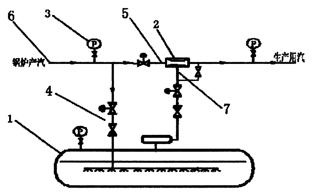
[0014] A steam heat accumulator system mainly includes a heat accumulator 1, a steam ejector 2, a pressure transmitter 3, a pressure regulating valve 4 and a steam pipeline 6. The main steam pipeline of the boiler conveys the boiler steam to the interior of the heat accumulator 1 through the regulating valve 4, and the steam produced by the boiler is connected to the high-pressure steam inlet 5 of the steam ejector through the regulating valve 4; the outlet of the heat accumulator 1 is adjusted The valve 4 is connected with the low-pressure steam inlet 7 of the steam ejector; the steam outlet pipe of the steam produced by the boiler, the heat accumulator 1 and the steam outlet pipe of the steam heat accumulator system are all equipped with a pressure transmitter 3 .

[0015] The boiler steam is transported to the interio...


PUM


Abstract

The invention relates to a steam heat accumulator system. The steam heat accumulator system mainly comprises a heat accumulator, a steam ejector, pressure transmitters, pressure regulating valves and a steam pipeline. According to the steam heat accumulator system, a boiler steam output pipeline is connected with an inlet of the steam heat accumulator; another boiler steam output pipeline is connected with a high pressure inlet of the steam ejector through one pressure regulating valve; an outlet of the heat accumulator is connected with a low pressure steam inlet of the steam ejector through the steam pipeline; a boiler steam generation and outlet pipeline, the heat accumulator and a steam heat accumulator system steam outlet pipeline are provided with the pressure transmitters respectively; the pressure regulating valves are arranged on the pipeline between the inlet of the heat accumulator and the steam ejector and the pipeline between the outlet of the heat accumulator and the steam ejector and used for controlling steam pressure of the heat accumulator and the inlet of the steam ejector. Through the steam ejection technology, high-pressure steam generated by a boiler is used for ejecting low-pressure steam inside the heat accumulator into the steam pipeline used for production so as to increase the difference between steam filling pressure and steam discharging pressure of the heat accumulator, so that the heat storage capacity of the heat accumulator per unit volume is effectively improved.

Description

technical field [0001] The invention relates to the fields of industrial production such as medicine, chemical fiber, food, printing and dyeing, and distributed energy, in particular to a steam heat storage system used for boiler steam production pressure higher than production steam pressure. Background technique [0002] Steam accumulators are widely used in industrial production fields such as medicine, chemical fiber, food, printing and dyeing, and distributed energy. They are mainly used to store excess steam during low-peak production steam. The thermal storage capacity of the steam accumulator is mainly determined by the pressure difference between the inlet and outlet of the accumulator and the volume of the accumulator. The operating condition of the steam accumulator is usually that the pressure difference between inlet and outlet is ≥0.3MPa. In the heating system, the design pressure and rated working pressure of the steam boiler are fixed. The production process ...

Claims


Application Information

Patent Timeline
Patent Type & Authority Applications(China)
IPC IPC(8): F22B37/00F22B35/00
CPCY02P80/15
Inventor 付红萍王立华李玉启赵玲玲
Owner 付红萍
Learn More