Vertical-type spiral particle waste heat recycling device and method for sintering waste heat power generation system

A technology of waste heat recovery device and waste heat power generation, which is applied in steam engine devices, waste heat treatment, machines/engines, etc. It can solve the problems of excessive resistance of the bottom air cap and cross air duct, gas-solid flow and temperature segregation, and low tank strength. , to achieve the effects of strong controllability of blanking, reduced operation difficulty, and improved heat transfer uniformity

Inactive Publication Date: 2014-09-17
ZHEJIANG UNIV
View PDF7 Cites 17 Cited by
  • Summary
  • Abstract
  • Description
  • Claims
  • Application Information

AI Technical Summary

Problems solved by technology

[0018] The purpose of the present invention is to provide a vertical sintering cooling device for the problems caused by the over-sealing of the lower part, the complexity of the device, the strength of the tank body is far too low, the resistance of the bottom air cap and the cross air channel is too large, and the gas-

Method used


Image

  • Vertical-type spiral particle waste heat recycling device and method for sintering waste heat power generation system
  • Vertical-type spiral particle waste heat recycling device and method for sintering waste heat power generation system
  • Vertical-type spiral particle waste heat recycling device and method for sintering waste heat power generation system

Examples


Embodiment Construction

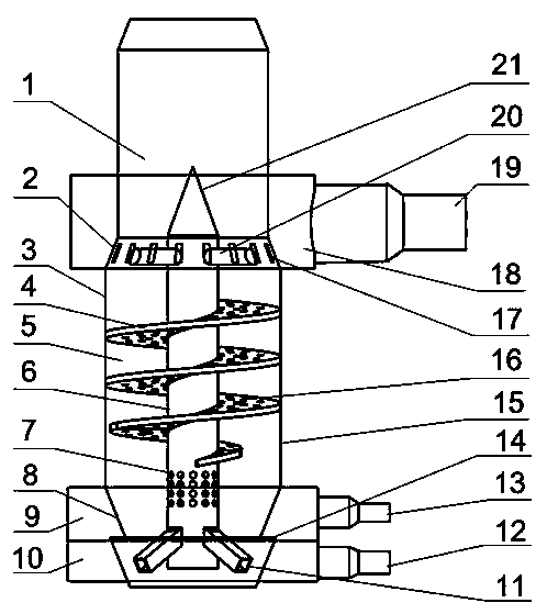
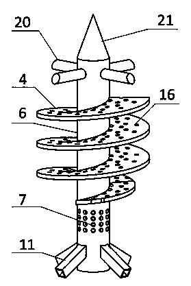
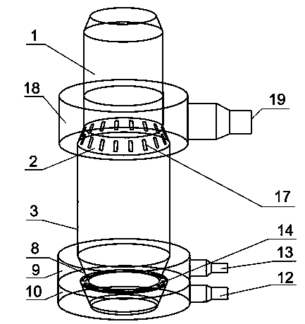
[0031] Such as figure 1 , 2 , 3, the vertical spiral particle waste heat recovery device for sintering waste heat power generation: including pre-storage section 1, chute section 2, cooling section 3, spiral feeding channel 4, heat exchange chamber 5, air supply body 6, central Air hole 7, lower cone section 8, upper air inlet chamber 9, lower air inlet chamber 10, cross air duct 11, lower air inlet pipe 12, upper air inlet pipe 13, annular air inlet 14, cooling section tank 15, blanking Road air hole 16, ramp section air hole 17, annular air outlet chamber 18, air outlet pipe 19, support rod 20, sharp cone 21;

[0032] The device body is sequentially provided with a pre-storage section 1, a chute section 2, a cooling section 3, and a lower cone section 8 from top to bottom; The body 6 is a cylinder with a hollow interior. The top of the air supply body 6 is provided with a sharp cone 21, and the upper part of the air supply body is provided with four support rods 20 in a cr...


PUM


Abstract

The invention discloses a vertical-type spiral particle waste heat recycling device and method for sintering waste heat generation. A device body is sequentially provided with a prestoring segment, a chute segment, a cooling segment and a lower conical segment from top to bottom. The device body is internally provided with an air supply body. The air supply body is a cylinder and is hollow. The top of the air supply body is provided with a pointed cone. The upper portion of the air supply body is provided with four cross-shaped supporting rods. The outer ends of the four supporting rods are fixedly connected with the chute segment. A heat exchange cavity is formed between the air supply body and a tank body of the cooling segment. The outer side of the middle of the air supply body is provided with a spiral discharging channel. The periphery of the upper portion of the spiral discharging channel is connected with the cooling segment. The lower portion of the air supply body is provided with an upward-inclined cross-shaped air channel. The cross-shaped air channel is connected with the lower portion of the lower conical segment. The bottom of the lower conical segment is provided with a bulkhead gate. A closed-type vibrating feeder is arranged below the bulkhead gate. The vertical-type spiral particle waste heat recycling device meets the specific requirement of sintering ore for a cooling device and is high in controllability, the service life of the vertical-type spiral particle waste heat recycling device is prolonged, gas resistance is reduced, flow and temperature uniformity are improved, and the waste heat utilization rate is improved.

Description

technical field [0001] The invention relates to a vertical spiral granule waste heat recovery device and method thereof for sintering waste heat power generation, in particular to a sinter vertical spiral granule waste heat recovery device and method in the fields of metallurgy and iron and steel industries. Background technique [0002] Sensible heat resources of sinter ore in the sintering process account for about 70% of the total waste heat resources in the sintering process, and improving the recovery and utilization rate of waste heat is the main direction of the recovery and utilization of waste heat in sintering. At present, the widely used ring or belt coolers have the following insurmountable disadvantages in the recovery and utilization of sensible heat: [0003] (1) High air leakage rate of cooling equipment [0004] The size of the gap at the air leakage site and the pressure difference inside and outside are the main factors affecting the air leakage rate. Am...

Claims


Application Information

Patent Timeline
IPC IPC(8): F27D17/00F01K11/02
CPCY02P10/25Y02P80/15
Inventor 俞自涛田付有黄连锋范利武屠柏锐尹德厚厉青
Owner ZHEJIANG UNIV
Why Eureka
Try Eureka