Method and system for field application and calibration of reflection fiber optic displacement sensor

A technology of displacement sensors and sensors, which is applied in the direction of instruments, optical devices, measuring devices, etc., can solve problems such as inability to establish on-site calibration, and achieve the effect of increasing accuracy, good stability and accuracy

Inactive Publication Date: 2014-09-17
INST OF GEOLOGY CHINA EARTHQUAKE ADMINISTRATION
View PDF5 Cites 7 Cited by
  • Summary
  • Abstract
  • Description
  • Claims
  • Application Information

AI Technical Summary

Problems solved by technology

[0008] The technical problem to be solved in this application is to provide a method and system for on-site calibration of reflective optical fiber displacement sensors,

Method used


Image

  • Method and system for field application and calibration of reflection fiber optic displacement sensor
  • Method and system for field application and calibration of reflection fiber optic displacement sensor
  • Method and system for field application and calibration of reflection fiber optic displacement sensor

Examples


Embodiment 1

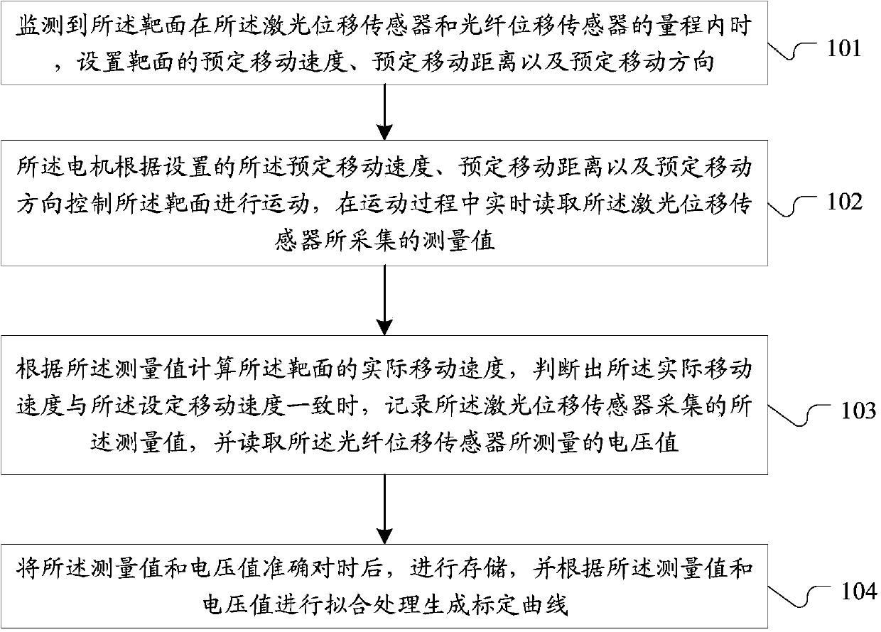
[0053] As shown in Figure 1, it is a method for on-site application calibration of a reflective optical fiber displacement sensor described in Embodiment 1 of the present application, which is applied to a calibration workbench including a target surface, a laser displacement sensor, an optical fiber displacement sensor and a motor on, including:

[0054] Step 101 , when it is detected that the target surface is within the measuring range of the laser displacement sensor and the optical fiber displacement sensor, a predetermined moving speed, a predetermined moving distance and a predetermined moving direction of the target surface are set.

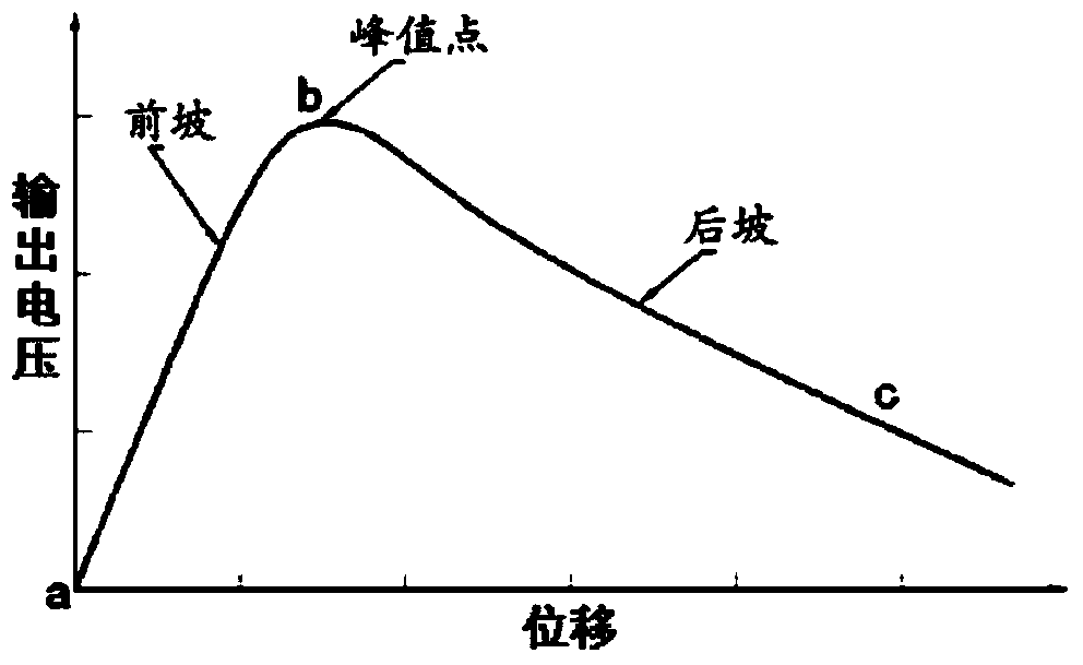
[0055] In the process of calibration measurement, if only one sensor is used for calibration, a sensor with a higher resolution or at least in the same order of magnitude is required as a calibration reference. Although the reading of the spiral micrometer can be used as the reference displacement value of the optical fiber displacement d...

Embodiment 2

[0069] For the on-site calibration method of the reflective optical fiber displacement sensor described in the first embodiment above, it is necessary to set up a corresponding calibration workbench, such as image 3 As shown, among them,

[0070] For this embodiment, the calibration performed by the optical fiber displacement sensor requires a workbench with high rigidity and stable structure. The calibration table is composed of optical fiber displacement sensor bracket, laser displacement sensor bracket, reflective target surface, pulse stepping motor and table, such as image 3 As shown, the optical paths of the laser displacement sensor and the optical fiber displacement sensor are kept parallel, the support is stable, and various materials to be calibrated can be installed on the reflective target surface. The surface properties of the material must be consistent with the application, and the target surface is perpendicular to the optical path of the sensor. The stepper...

Embodiment 3

[0084] Such as Image 6 As shown, it is a system for on-site application calibration of a reflective optical fiber displacement sensor described in Embodiment 3 of the present application, which is applied to a calibration workbench including a target surface, a laser displacement sensor, an optical fiber displacement sensor and a motor, including : a preprocessing unit 601, a drive processing unit 602, a measurement processing unit 603, and a rendering unit 604; wherein,

[0085] The preprocessing unit 601 is coupled with the drive processing unit 602, and is used to set the predetermined moving speed and predetermined moving distance of the target surface when it is detected that the target surface is within the range of the laser displacement sensor and the optical fiber displacement sensor and the intended direction of movement.

[0086] In the process of calibration measurement, if only one sensor is used for calibration, a sensor with a higher resolution or at least in ...


PUM


Abstract

The invention discloses a method and system for field application and calibration of a reflection fiber optic displacement sensor. The method includes the steps that when a target surface is monitored to be in the range of a laser displacement sensor and the fiber optic displacement sensor, the preset moving speed, the preset moving distance and the preset moving direction of the target surface are set; a motor controls the target surface to move according to the preset moving speed, the preset moving distance and the preset moving direction, and the measurement value collected by the laser displacement sensor is read in real time in the moving process; the actual moving speed of the target surface is calculated according to the measurement values, and when the actual moving speed is judged to be consistent with the set moving speed, the measurement value collected by the laser displacement sensor is recorded, and the voltage value measured by the fiber optic displacement sensor is read; accurate time hack is conducted on the measurement value and the voltage value, then storage is conducted, and fitting is conducted according to the measurement value and the voltage value to generate a calibration curve. The method and system for field application and calibration of the reflection fiber optic displacement sensor solve the problem that a fast and high-precision field suitable for different reflection conditions for calibration cannot be built at present.

Description

technical field [0001] The present application relates to the technical field of reflective optical fiber displacement sensing, in particular to a method and system for field application calibration of reflective optical fiber displacement sensors. Background technique [0002] Reflective optical fiber displacement sensing technology is a continuous light source as the measurement carrier, the light intensity as the measurement signal, and the optical fiber as the propagation medium. By sensing the measured signal and distinguishing the relationship between the received signal and the transmitted signal, the displacement of the measured object can be obtained. Technology (references: Cong Hong, reflective optical fiber micro-displacement sensor. 2003). Compared with other displacement sensors, optical fiber displacement sensors have the characteristics of high frequency response (high sensitivity), non-contact measurement, small size, simple structure, anti-electrical interf...

Claims


Application Information

Patent Timeline
IPC IPC(8): G01B11/02
Inventor 李世念卓燕群汲云涛刘力强
Owner INST OF GEOLOGY CHINA EARTHQUAKE ADMINISTRATION
Why Eureka
Try Eureka