Spot welding fiber bragg grating strain sensor and installation method thereof

A strain sensor and fiber grating technology, applied in the sensor field, can solve the problems of reduced stability, short welding distance, sensitive grid corrosion, etc., and achieve the effects of improving measurement accuracy, anti-electromagnetic interference, and fast response speed.

Active Publication Date: 2014-09-17
STATE GRID HENAN ELECTRIC POWER ELECTRIC POWER SCI RES INST +2
View PDF5 Cites 14 Cited by
  • Summary
  • Abstract
  • Description
  • Claims
  • Application Information

AI Technical Summary

Problems solved by technology

The problem is that the resistance strain gauge is susceptible to electromagnetic interference and has a short life, so it is difficult to apply for long-term monitoring
The problem is that if the resistance strain gauge gets wet, the insulation resistance and bonding strength will be reduced, and in severe cases, the sensitive grid will be corroded; the intrusion of acid, alkali and oil will even change the physical properties of the substrate and adhesive
[0013] There are generally two problems in the existing spot-welded fiber grating strain sensors: one is that due to the large thickness gap of the fiber grating substrate, welding is difficult and the welding distance is very short; the other is that there is a large creep when using ordinary epoxy resin glue changes, reducing the stability of long-term measurements

Method used


Image

  • Spot welding fiber bragg grating strain sensor and installation method thereof
  • Spot welding fiber bragg grating strain sensor and installation method thereof
  • Spot welding fiber bragg grating strain sensor and installation method thereof

Examples


Embodiment Construction

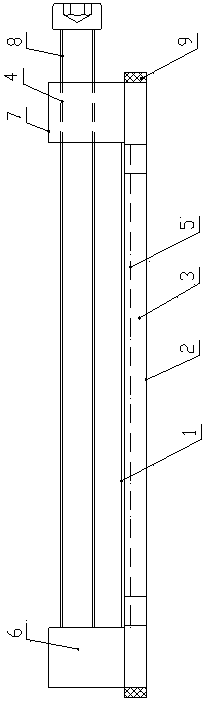
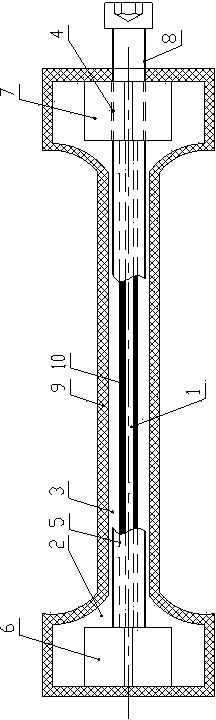
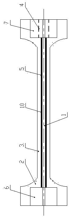
[0033] Such as figure 1 As shown, the present invention includes a fiber grating strain sensor 1 and a base body 2. The base body 2 is made of a highly elastic alloy material. The base body 2 includes a base plate 3 and two adjustment blocks integrally connected to the left and right ends of the base plate 3. The two adjustment blocks are respectively left adjustment blocks. Block 6, right adjustment block 7, a base body groove 5 is provided in the middle part of the base body 3 between the two adjustment blocks, and the fiber grating strain sensor 1 is installed in the base body groove 5. There is a layer of encapsulation layer 10 on the outside of the grating strain sensor 1, and the material of the encapsulation layer 10 is glass powder with low melting point. The lower half of the encapsulation layer 10 is connected to the groove 5 of the substrate, thereby encapsulating the grating strain sensor 1 .

[0034] Adjustment hole 4 is horizontally arranged on right adjustment ...


PUM


Abstract

The invention discloses a spot welding fiber bragg grating strain sensor. The spot welding fiber bragg grating strain sensor comprises a fiber bragg grating strain sensor body and a base body made of high-elasticity alloy materials, wherein the base body comprises a substrate, a left regulating block and a right regulating block, the left regulating block and the right regulating block are connected with the left end and the right end of the base body respectively in an integrated mode, a base body groove is formed in the middle of the position, between the two regulating blocks, of the base body, the outer side of the fiber bragg grating strain sensor body is provided with a packaging layer made of low-melting-point glass powder, and the lower half portion of the packaging layer is connected with the base body groove; the right regulating block is transversely provided with a regulating hole, a regulating bolt penetrates through the regulating hole, and the left end of the regulating bolt abuts against the right side face of the left regulating block; the periphery of the substrate is provided with a rubber layer used for sealing. As the spot welding fiber bragg grating strain sensor is obviously superior to a traditional resistance strain gage, the purpose that the real-time state of strain of an iron tower electric transmission line is known comprehensively for a long time is achieved.

Description

technical field [0001] The invention relates to the field of sensors. Background technique [0002] With the continuous progress of human society, daily life relies more and more on electricity, and the smooth transmission of electricity is the guarantee of people's normal life. The damage of transmission lines due to natural and man-made causes has a huge impact on people's daily life. [0003] Due to the change of meteorological conditions, the external load of the transmission line in the external environment also changes. One of the external loads that plays a major role in damage is strong wind. The balance state of the transmission line tower installed in the field under the galloping condition is a dynamic process. These will directly affect the foundation, tower, and span of the high-voltage transmission line tower, and further cause deformation of other elements of the high-voltage transmission line, or even collapse the tower. Since this is a slow process, by mo...

Claims


Application Information

Patent Timeline
Patent Type & Authority Applications(China)
IPC IPC(8): G01B11/16
Inventor 马东方耿进锋蔡红生张留斌
Owner STATE GRID HENAN ELECTRIC POWER ELECTRIC POWER SCI RES INST
Why Eureka
Try Eureka