
Wellhead detection unit for drilling tool screw thread stress conditions

A detection device and thread technology, applied in the direction of force measurement, material magnetic variable, etc. by measuring the change of magnetic properties of materials caused by applied stress, can solve the problems of difficult to reach the root of the internal thread, difficult to achieve, and large wall thickness. The effect of reducing detection errors, fast detection speed and high structural strength

Active Publication Date: 2014-09-17
PETROCHINA CO LTD
View PDF5 Cites 6 Cited by
  • Summary
  • Abstract
  • Description
  • Claims
  • Application Information

AI Technical Summary

Problems solved by technology

Due to the relatively complex geometric structure and large wall thickness of the threaded part, the existing conventional non-destructive testing techniques are obviously insufficient in the early diagnosis of abnormal stress concentration and microcracks in the internal threaded part of the drilling tool.
[0003] For example: (1) The good surface contact conditions and coupling medium conditions required for ultrasonic testing are difficult to achieve in the threaded part, resulting in very unsatisfactory testing results;
[0004] (2) Magnetic flux leakage detection technology requires the detection probe to be in close contact with the surface to be tested, and its detection effect is greatly limited in thread parts with relatively complex geometric structures;
[0005] (3) Among the existing non-destructive stress detection methods, the penetration depth of X-ray diffraction technology is only tens of microns, and it is difficult to touch the root of the internal thread. Magnetoacoustic emission, Barkhausen noise and magnetic stress detection methods all require electromagnetic The excitation condition (coil), the combined structure of the excitation coil and the detection probe is too large, it is impossible to distinguish the stress state of the variable diameter point and the root of the internal thread, and it is difficult to obtain application in thread detection
[0006] Existing practice has proved that the existing non-destructive testing techniques (such as eddy current, ultrasonic, X-ray, etc.) are more effective in detecting the macroscopic defects that have appeared, but they cannot detect the fatigue damage from the source of fatigue damage (microscopic defects and stress concentration areas). Make an early assessment of the technical status of the drilling tool to prevent accidental damage to the drilling tool

Method used


Image

  • Wellhead detection unit for drilling tool screw thread stress conditions
  • Wellhead detection unit for drilling tool screw thread stress conditions
  • Wellhead detection unit for drilling tool screw thread stress conditions

Examples


Embodiment 1

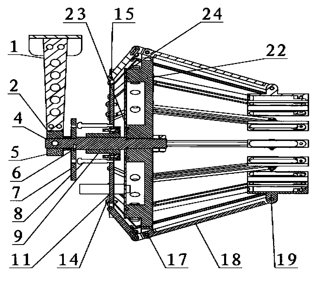
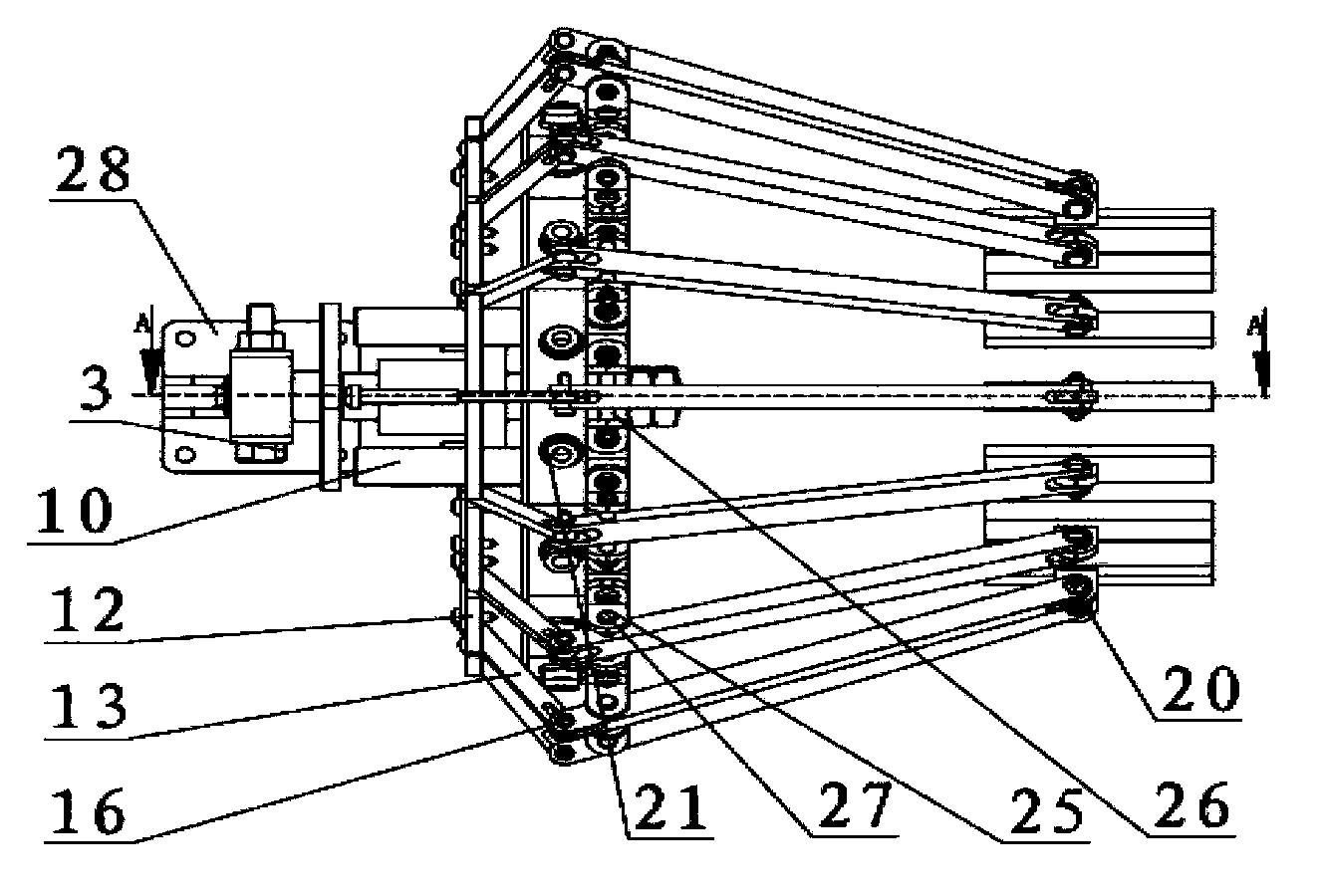
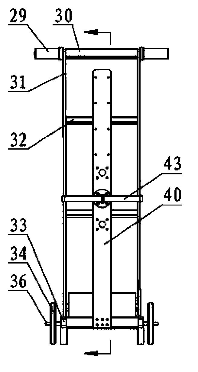
[0026] Embodiment 1: as figure 1 , figure 2 , image 3 , Figure 4 as shown,

[0027] A wellhead detection device for the thread stress state of drilling tools. The rib plate 1 is fixed with the conversion block 2 by screws, and the conversion block 2 and the main shaft 4 are fixed by M8 bolts 3. Insert it into the light hole of the main shaft 4, the right side of the rotating ring 7 and the shoulder of the main shaft 4 and the left side are fixed with the copper sleeve 5, the rotating ring 7 can only rotate tangentially and be fixed in the axial direction, and the positioning pin shaft 6 is limited The rotation angle of the rotating ring 7 is 45°, the threaded connection between the lower end of the bearing nail 8 and the umbrella rod disc 12 is threaded, the flange linear bearing 9 and the umbrella rod disc 12 are connected by bolts, and the bearing nail 8 faces left along the axis of the main shaft 4 The movement drives the umbrella pole disc 12 to move axially to the ...

Embodiment 2

[0030] Embodiment 2: as figure 1 , figure 2 , image 3 , Figure 4 as shown,

[0031] A drilling tool thread stress state wellhead detection device, comprising a drilling tool joint thread detection device, a linear guide rail, a drilling tool joint outer diameter centering mechanism, a carrying trolley, a power supply, an instrument control box, including a positioning rod flange base 41, a centering Shaft 42, centering clip 43, positioning rod flange base 41 is fixed on the support plate 40, centering clip 43 is fixed on the centering shaft 42 by screws, and centering shaft 42 is inserted into the travel hole of the positioning flange base 41;

[0032] The drilling tool joint threaded wellhead detection device includes a rib plate 1, a conversion block 2, a main shaft 4, a copper sleeve 5, a positioning pin shaft 6, a rotating ring 7, a bearing nail 8, a flange linear bearing 9, a wall sealing joint 10, and a steel ring Cover sheet 11, umbrella pole disk 12, umbrella po...


PUM


Abstract

A wellhead detection unit for drilling tool joint screw thread stress conditions belongs to the field of nondestructive testing, and comprises a drilling tool joint screw thread detection device, a linear guide rail, a drilling tool joint outer-diameter centering mechanism, a bearing trolley, a power source and an instrument control box; the drilling tool joint outer-diameter centering mechanism comprises a positioning rod flange base, a centering shaft and a centering clamp, and the positioning rod flange base is fixed on a supporting plate, the centering clamp is fixed onto the centering shaft through a screw, the centering shaft is inserted into a stroke hole of the positioning rod flange base; the drilling tool joint screw thread wellhead detection device comprises a rib plate, a conversion block, a main shaft, a copper sleeve, a positioning pin shaft, a rotating ring, a bearing screw, a flange linear bearing, a through-wall sealing joint, a steel ring cover plate, an umbrella rod disk, an umbrella rod, a steel ring, a swing rod, a sensor seal box and a sealing joint; the wellhead detection unit for drilling tool joint screw thread stress conditions is stable in the structure, high in structural strength, abrasion resistant, fast in detection speed, high in detection precision, and capable of realizing fast and accurate screw thread detection of large scale joints.

Description

technical field [0001] The invention relates to a wellhead detection device applied to the thread stress condition of a drill tool joint. It has strong applicability to detect the internal thread from the outer wall of the drill tool joint while satisfying the detection of the external thread from the outer diameter of the drill tool joint. The high-efficiency thread stress state detection tool required for drilling use can accurately detect and evaluate the thread stress state of wellhead drill tool joints, and belongs to the field of nondestructive testing of drilling tools. Background technique [0002] At present, one of the main manifestations of drilling tool failure is the fracture and damage of the connecting thread part. The fracture crack of the external thread joint often occurs at the root of the second or third thread from the step, and the fracture crack of the internal thread joint often occurs at the At the turnbuckle of the last part to engage. The thread p...

Claims


Application Information

Patent Timeline
Patent Type & Authority Applications(China)
IPC IPC(8): G01N27/82G01L1/12
Inventor 苏建文祖强卢强葛保胜陈家磊牟鹤林丁毅樊建春张来斌
Owner PETROCHINA CO LTD
Learn More