Method for positioning artificial wetland clogging area through resistivity curve

A technology of artificial wetlands and resistivity, which is applied in the directions of electric/magnetic exploration, utilization of re-radiation, re-radiation of sound waves, etc.

Inactive Publication Date: 2014-09-17
GUILIN UNIVERSITY OF TECHNOLOGY
View PDF0 Cites 27 Cited by
  • Summary
  • Abstract
  • Description
  • Claims
  • Application Information

AI Technical Summary

Problems solved by technology

[0005] The purpose of the present invention is to solve the clogging problem in constructed wetlands, and provide a method for locating clogged areas in constructed wetlands using resistivity curves or comparative resistivity curves.

Method used


Image

  • Method for positioning artificial wetland clogging area through resistivity curve
  • Method for positioning artificial wetland clogging area through resistivity curve
  • Method for positioning artificial wetland clogging area through resistivity curve

Examples


Embodiment 1

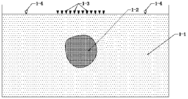
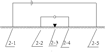
[0028] (1) if figure 1 , 2 As shown, firstly, the resistivity sounding point 1-3 is arranged above the suspected blockage area 1-2, and the DC resistivity symmetrical quadrupole sounding device is used for measurement. The distance between the measuring electrode M2-2 and the measuring electrode N2-3 is 10 cm, and the power supply The positive electrode A2-1 of the electrode and the negative electrode B2-5 of the power supply electrode are from 0.2m to 2m with a difference of 10cm, press figure 2 The DC resistivity symmetric quadrupole sounding device shown conducts resistivity sounding of the point from shallow to deep.

[0029] (2) The positive electrode A2-1 of the power supply electrode, the negative electrode B2-5 of the power supply electrode, the measurement electrode M2-2, and the measurement electrode N2-3 of the DC resistivity symmetrical quadrupole sounding device are all arranged symmetrically on both sides of the measuring point O2-3, Every time the electrode s...

Embodiment 2

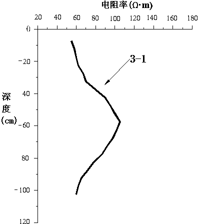
[0035] In this embodiment, the comparative resistivity curve is used to locate the clogged area of ​​the constructed wetland.

[0036] (1) if figure 1 , 2 As shown, firstly, the resistivity sounding point 1-4 is arranged above the area 1-1 determined to be unblocked in the constructed wetland, and the DC resistivity symmetrical quadrupole sounding device is used for measurement, the measuring electrode M2-2 and the measuring electrode N2-3 The distance is 10cm, the positive pole of the power supply electrode A2-1 and the negative pole of the power supply electrode B2-5 are from 0.2m to 2m with a difference of 10cm, press figure 2 The DC resistivity symmetric quadrupole sounding device shown conducts resistivity sounding of the point from shallow to deep.

[0037] (2) The positive electrode A2-1 of the power supply electrode, the negative electrode B2-5 of the power supply electrode, the measurement electrode M2-2, and the measurement electrode N2-3 of the DC resistivity sym...

Embodiment 3

[0044] In this embodiment, it is assumed that we do not know the clogged area of ​​the constructed wetland at all, that is, the approximate location of the suspected clogged area of ​​the constructed wetland cannot be determined, and the blocked area of ​​the constructed wetland is located using the resistivity bathymetry curve type map.

[0045] (1) if figure 1 As shown, if you do not know the approximate location of 1-2, first arrange the resistivity sounding points evenly above the artificial wetland at a distance of about 50cm, and use the DC resistivity symmetrical quadrupole sounding device to measure, and the measuring electrode M2-2 The distance between the measuring electrode N2-3 and the measuring electrode N2-3 is 10cm, and the positive pole of the power supply electrode A2-1 and the negative pole of the power supply electrode B2-5 are from 0.2m to 2m with a difference of 10cm, press figure 2 The DC resistivity symmetric quadrupole sounding setup shown takes resist...


PUM

PropertyMeasurementUnit
electrical resistivityaaaaaaaaaa

Abstract

The invention discloses a method for positioning an artificial wetland clogging area through a resistivity curve. The method includes the steps that first, a direct-current resistivity symmetrical four-pole sounding device is arranged above an artificial wetland, and the apparent resistivity is measured according to the mode that the electrode spacing becomes bigger and bigger; second, a power supply positive electrode A, a power supply negative electrode B, a measurement electrode M and a measurement electrode N of the direct-current resistivity symmetrical four-pole sounding device are all arranged symmetrical about a measurement point, and the apparent resistivity (please see the formula in the specification) of the electrode spacing is calculated every time the power supply electrode spacing is changed; third, the measured apparent resistivity is subjected to inversion, and the resistivity depth measurement curve is drawn according to the resistivity values obtained through inversion; fourth, the non-clogging area of the artificial wetland has the low resistivity characteristic, the clogging area of the artificial wetland has the high resistivity characteristic, and on the resistivity depth measurement curve, the vertical spatial position of the clogging area in the measurement point is determined according to the changing characteristic of the resistivity value. According to the method, on the basis of the conductivity difference of dielectric, the artificial wetland clogging area can be positioned through the resistivity difference.

Description

technical field [0001] The invention belongs to the technical field of sewage treatment, and in particular relates to a method for locating blocked areas of artificial wetlands by using resistivity curves. Background technique [0002] Constructed wetland sewage treatment technology is a new ecological engineering technology for sewage treatment that emerged in the 1970s. It has the advantages of good flexibility, low investment, low energy consumption, strong decontamination ability, convenient management, and no secondary pollution. Applications are increasingly common. However, in recent years, problems such as clogging frequently occur in constructed wetlands during operation, the purification performance decreases, and the service life is shortened. For example, among the 355 subsurface flow constructed wetlands in the United States and the United Kingdom, nearly half of them were blocked within five years of use, and the hydraulic conductivity of the filler dropped sh...

Claims


Application Information

Patent Timeline
Patent Type & Authority Applications(China)
IPC IPC(8): G01V3/04G01N27/04
Inventor 丁彦礼白少元熊彬
Owner GUILIN UNIVERSITY OF TECHNOLOGY
Why Eureka
Try Eureka