
Wet etching process and equipment, and solar cell and manufacturing method thereof

A technology for solar cells and solar cells, applied in the field of solar energy, can solve the problems of etching black lines and rising square resistance, and achieve the effects of improving electrical performance parameters, reducing use costs, and achieving good polishing effects.

Inactive Publication Date: 2014-09-17
BEIJING NAURA MICROELECTRONICS EQUIP CO LTD
View PDF3 Cites 24 Cited by
  • Summary
  • Abstract
  • Description
  • Claims
  • Application Information

AI Technical Summary

Problems solved by technology

[0006] The invention provides a wet etching process, equipment, a solar cell and a manufacturing method thereof, which solves the problems of etching black lines and rising square resistance existing in the existing wet etching process, and realizes the integration of the phosphosilicate glass layer and the solar cell. At the same time as the back junction is removed, the purpose of back polishing can also be achieved, thereby improving the conversion efficiency of solar cells

Method used


Image

  • Wet etching process and equipment, and solar cell and manufacturing method thereof
  • Wet etching process and equipment, and solar cell and manufacturing method thereof
  • Wet etching process and equipment, and solar cell and manufacturing method thereof

Examples


Embodiment 1

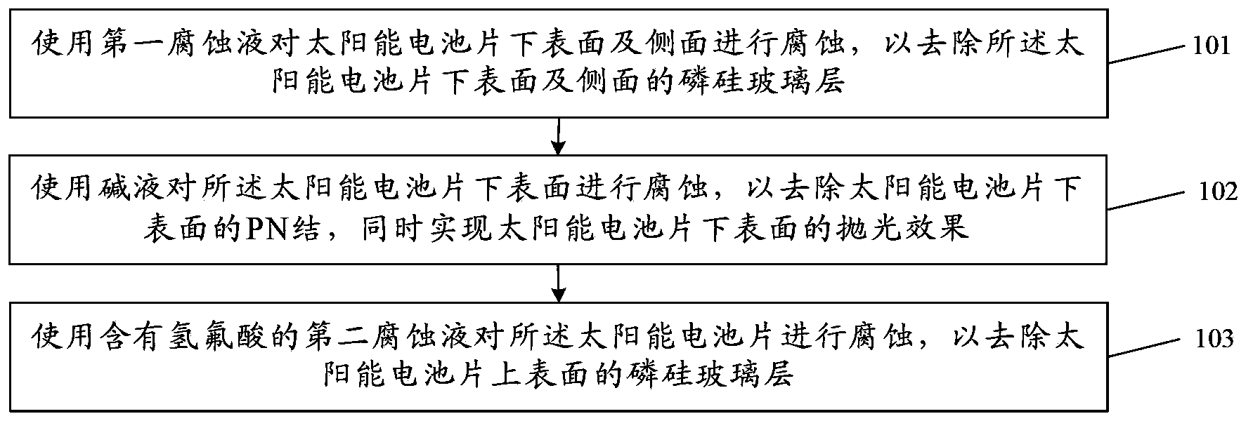
[0055] Embodiments of the present invention provide a wet etching process, such as figure 2 shown, including:

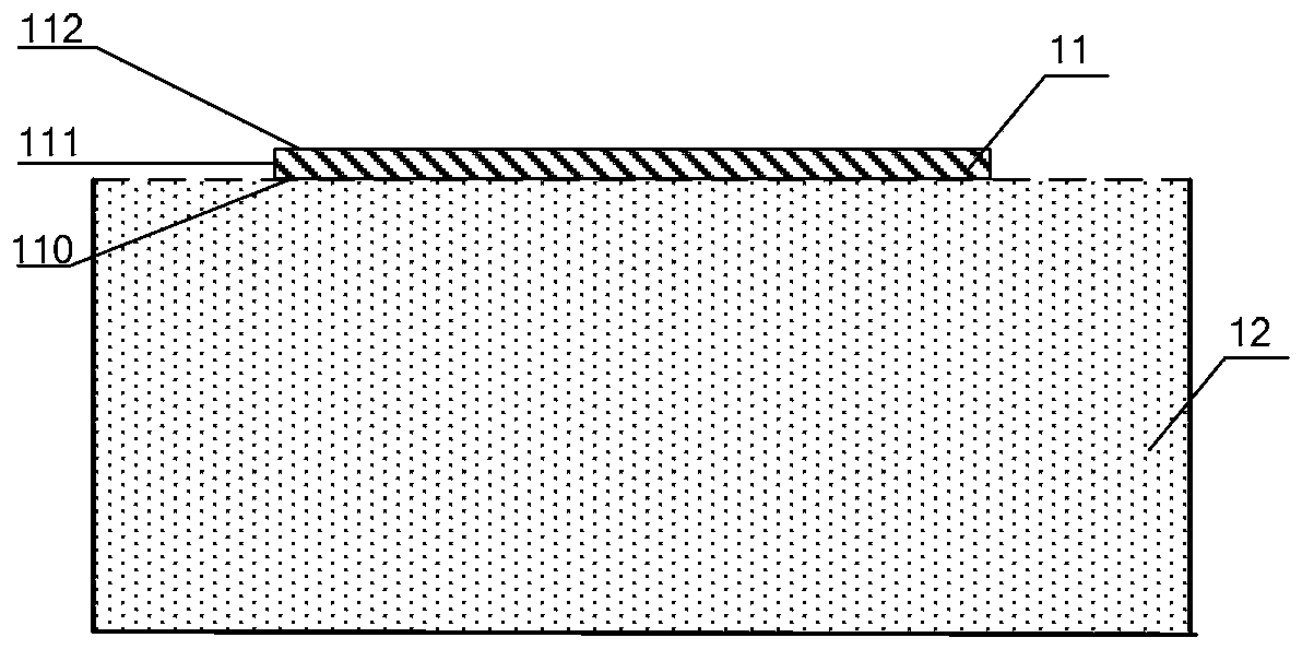
[0056] 101. If image 3 As shown, the lower surface 110 and the side surface 111 of the solar battery sheet 11 are etched and etched using the first etching solution 12 to remove the phosphosilicate glass layer on the lower surface 110 and the side surface 111 of the solar battery sheet 11. The first etching solution 12 is hydrofluoric acid solution;

[0057] In this embodiment, the upper surface (front side) 112 of the solar battery sheet 11 refers to the side of the solar battery sheet 11 that is finally formed with a PN junction, and the lower surface (back or backlight surface) 110 of the solar battery sheet 11 refers to the uppermost surface of the solar battery sheet 11. The other surface opposite to the upper surface 112 , the side surface 111 refers to the connection surface between the upper surface 112 and the lower surface 111 .

[0058] In this step, ...

Embodiment 2

[0089] For crystalline silicon solar cells, the phosphosilicate glass layer formed after diffusion is a recombination region for carriers and must be removed. In the existing etching process, the removal of the back junction is carried out in the etching tank, and hydrofluoric acid and nitric acid are used for reaction etching. However, the reaction between silicon and acid is an isotropic reaction, and the reaction rate is very fast. Therefore, in order to ease the reaction rate and prevent the backside corrosion from being too strong, the proportion concentration of the acid in the etching tank should not be too high, and it is required to be carried out at a low temperature, in order to achieve the back junction can be completely corroded, and at the same time, it will not affect the front PN. The effect of causing adverse effects. Since the depth of the PN junction on the back is very shallow (generally within 0.3um), after wet etching, the corrosion degree on the back of ...

Embodiment 3

[0112] In addition, the present invention also provides a solar cell, comprising a substrate having a P-type layer and an N-type layer, one side of the substrate has a back electrode, and the other side of the substrate has an anti-reflection film, and the anti-reflection film There is a front electrode passing through the anti-reflection film and in contact with the substrate, and the solar cell undergoes any wet etching process described in Embodiment 1 during the manufacturing process.

[0113] Compared with the prior art, the solar cell mentioned in the present invention removes the phosphosilicate glass layer and completes the back junction and back polishing at the same time during the manufacturing process. The electrical performance parameters have been improved.


PUM


Abstract

The invention, which relates to the technical field of the solar energy, discloses a wet etching process and equipment, and a solar cell and manufacturing method thereof. Therefore, problems of etching black line occurrence and square resistance increasing according to the existing wet etching process can be solved; and elimination of the phosphorosilicate glass layer and the back junction is realized and an objective of back polishing is achieved, thereby improving the conversion efficiency of the solar cell. The wet etching process comprises the following steps that: first corrosive liquid is used for carrying out corrosion on the lower surface and the side surface of a solar cell so as to remove the phosphorosilicate glass layer at the lower surface and the side surface of the solar cell, wherein the first corrosive liquid is a hydrofluoric acid solution; alkali liquor is used for carrying out corrosion on the lower surface of the solar cell so as to remove the PN junction at the lower surface of the solar cell and realize the polishing effect of the lower surface f the solar cell; and second corrosive liquid containing hydrofluoric acid is used for carrying out corrosion on the solar cell, thereby removing the phosphorosilicate glass layer at the upper surface of the solar cell.

Description

technical field [0001] The invention relates to the technical field of solar energy, in particular to a wet etching process and wet etching equipment used in the manufacture of solar cells, and also relates to a solar cell and a manufacturing method thereof. Background technique [0002] Solar energy is an inexhaustible renewable energy source for human beings, and it is also a clean energy source. To this end, various solar cells have been researched and developed. Among them, crystalline silicon solar cells have the highest conversion efficiency, the fastest development, the most mature technology, and have been widely used. [0003] The production process of crystalline silicon solar cells mainly includes silicon wafer cleaning; texturing; diffusion making PN junction; etching; deposition of silicon nitride anti-reflection film; preparation of electrodes by screen printing; high temperature sintering; Among them, the process of diffusion PN junction generally uses POCl ...

Claims


Application Information

Patent Timeline
Patent Type & Authority Applications(China)
IPC IPC(8): H01L31/18
CPCH01L21/02016H01L21/02019H01L21/67075H01L31/068H01L31/1804Y02E10/547Y02P70/50
Inventor 吴鑫
Owner BEIJING NAURA MICROELECTRONICS EQUIP CO LTD
Learn More