Liquid-cooled permanent magnet coupler

A permanent magnet coupler, liquid cooling technology, used in cooling/ventilation devices, electrical components, electromechanical devices, etc., can solve the problems of limited power and speed range, and achieve optimized cooling channel technology, low processing cost, Noise reduction effect

Inactive Publication Date: 2014-09-17
SUZHOU SIFURUI ENERGY SAVING TRANSMISSION TECH
View PDF4 Cites 2 Cited by
  • Summary
  • Abstract
  • Description
  • Claims
  • Application Information

AI Technical Summary

Problems solved by technology

These problems limit the power and speed

Method used


Image

  • Liquid-cooled permanent magnet coupler
  • Liquid-cooled permanent magnet coupler
  • Liquid-cooled permanent magnet coupler

Examples


Example Embodiment

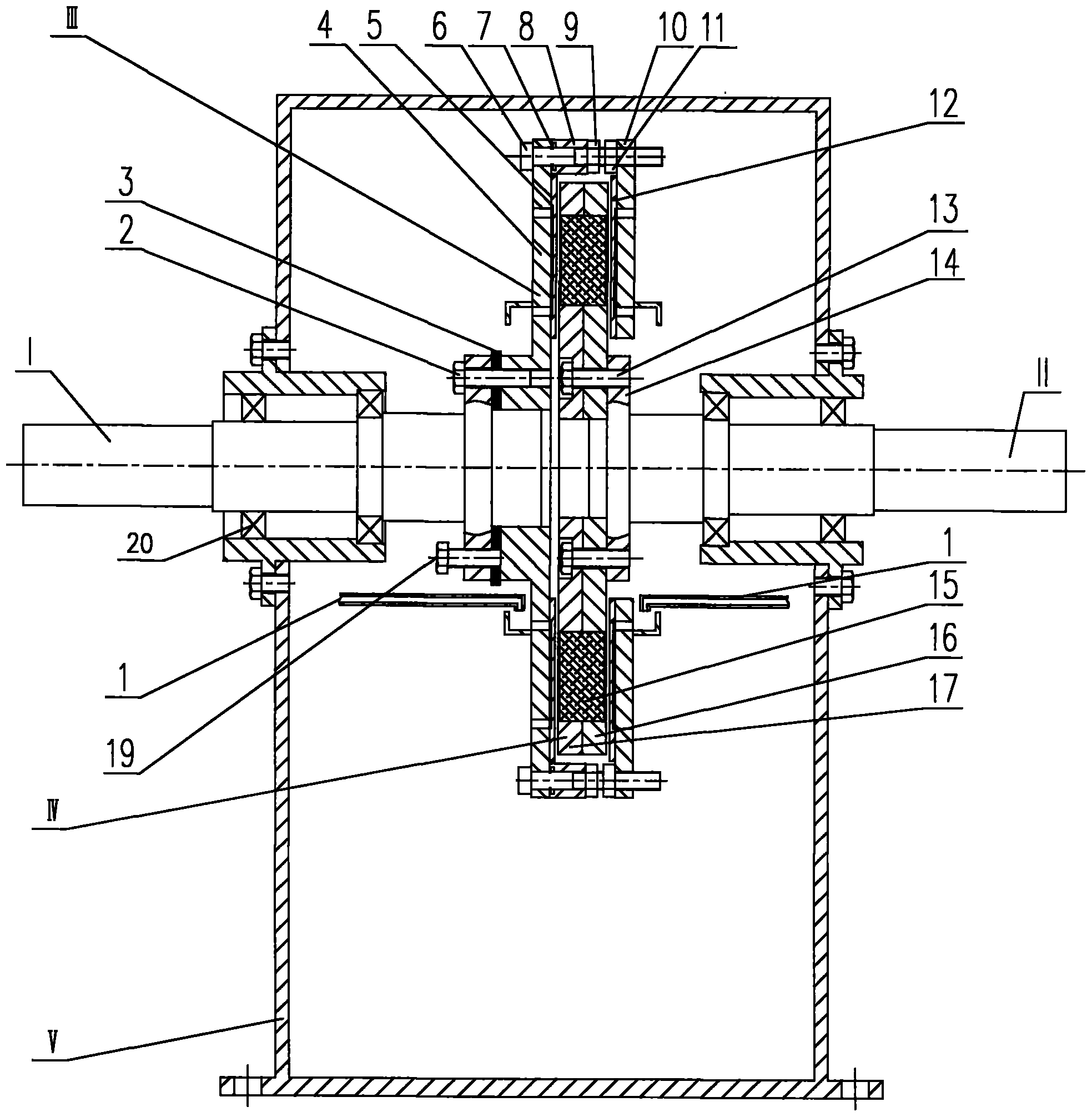
[0021] It should be noted that the structures, proportions, sizes, etc. shown in the accompanying drawings of the specification are only used to cooperate with the specific embodiments, so that those skilled in the art can understand the concept of the present invention more clearly, and are not used to limit the protection scope of the present invention. . Any structural modification, proportional relationship change, or size adjustment should still fall within the protection scope of the present invention without affecting the efficacy and purpose of the present invention. For ease of description, the relative position relationship of each component is described according to the layout direction of the drawings in the specification. For example, the position relationship of up, down, left, and right is determined according to the layout direction of the drawings in the specification.

[0022] In order to make the objectives, technical solutions and advantages of the present inv...


PUM


Abstract

The invention provides a liquid-cooled permanent magnet coupler. The liquid-cooled permanent magnet coupler comprises two groups of magnetic disks which are arranged oppositely. Conductive disks are compressed tightly on the opposite surfaces of the magnetic disks through a mould pressing technology. The surfaces, close to the magnetic disks, of the conductive disks are provided with cooling liquid flow channels, liquid grooves, liquid inlet holes and liquid outlet holes are formed in the magnetic disks, the liquid grooves are communicated with the liquid inlet holes, cooling liquid enters the liquid inlet holes under the effect of centrifugal force after entering the liquid grooves though a cooling oil pipe, and the liquid inlet holes and the liquid outlet holes are communicated with the cooling liquid flow channels. Through the liquid-cooled permanent magnet coupler, heat generated on the conductive disks by eddy currents can be taken away timely, the temperature of the conductive disks and the temperature of the magnetic disks can be controlled to be at a low degree, and magnets are not prone to demagnetization. Thus, noise generated when equipment runs is reduced.

Description

technical field [0001] The invention relates to the field of energy-saving transmission, in particular to a liquid-cooled permanent magnetic coupler. Background technique [0002] The permanent magnet coupler realizes the torque transmission from the motor to the load through the air gap between the copper conductor and the permanent magnet. This technology enables no mechanical link between the driving (motor) and driven (load) sides. Its working principle is that the rare metal oxide boron iron neodymium permanent magnet at one end interacts with the induced magnetic field at the other end to generate torque, which is not affected by the small angle or small offset between the motor shaft and the load shaft due to installation misalignment. Influence. The vibration problem caused by the center asymmetry is eliminated. Since there is no mechanical link, even the vibration caused by the motor itself will not cause the load vibration, so that the vibration problem of the wh...

Claims


Application Information

Patent Timeline
IPC IPC(8): H02K51/00H02K9/00
Inventor 邓高见陈力
Owner SUZHOU SIFURUI ENERGY SAVING TRANSMISSION TECH
Why Eureka
Try Eureka