Low melting point alloy casting clamp for processing thin-walled parts, and use method thereof
A technology of thin-walled parts and low melting point, which is applied in the field of low melting point alloy casting fixtures. It can solve the problems of cutting tool, affecting the dimensional accuracy of the workpiece, surface roughness of position accuracy, and increasing the difficulty of fixture manufacturing, so as to facilitate clamping and pressing. , Clamping stability is improved, and the effect of large margin cutting is realized
Active Publication Date: 2014-09-24
西安西航集团莱特航空制造技术有限公司
View PDF8 Cites 13 Cited by
- Summary
- Abstract
- Description
- Claims
- Application Information
AI Technical Summary
Problems solved by technology
1. The design datum of thin-walled shell parts is usually not the surface or circle on the part, but a relatively independent point. If the clamping and positioning follow the principle of unified datum, the design datum and processing datum will coincide, and the datum point on the part will be used for positioning , the reliability of positioning will be reduced, the difficulty of fixture manufacturing will increase, and workers will spend a long time when clamping parts
2. The large internal cavity of thin-walled shell parts leads to poor rigidity. When milling these parts, the problem often occurs: when the milling cutter reaches the cavity part, due to the poor rigidity of the cavity part, the shell moves back when receiving cutting force. Shrinkage, the cutting depth of the tool is given to 0.5mm, and the dimensional change of the part after milling is only 0.1mm or less; while the rigid part is cut by 0.5mm, the actual dimensional change is 0.5mm
The result is that the size of the part with good rigidity is out of tolerance, the size of the part with poor rigidity has not yet arrived, and the qualified rate of parts is low
3. The low processing efficiency of thin-walled shell parts is a common consensus within the industry. To improve efficiency, the cutting amount and cutting speed must be increased. However, with the change of processing parameters, the processing state of parts is unstable. Phenomena such as large changes
Under the action of cutting force, the processing of cast superalloy thin-walled shell parts is easy to cause thermal deformation, vibration and residual stress to cause deformation, which affects the dimensional accuracy, position accuracy and surface roughness of the workpiece. It is easy to deform, and there will be vibration of the knife and part movement during processing, which will easily lead to out-of-tolerance scrapping. Therefore, how to improve the efficiency and surface integrity in the processing of thin-walled shell parts is a goal pursued by various countries. It is reasonable Clamping parts becomes the key to improving processing quality and efficiency
Method used
View moreImage
Smart ImageViewing Examples
Examples
Embodiment
Login to View More PUM
| Property | Measurement | Unit |
|---|---|---|
| melting point | aaaaa | aaaaa |
| melting point | aaaaa | aaaaa |
Abstract
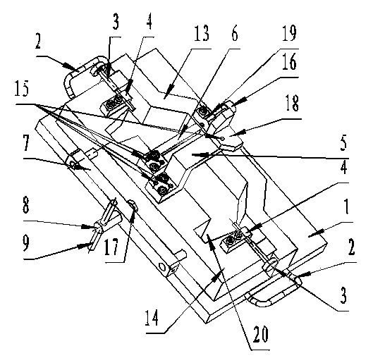
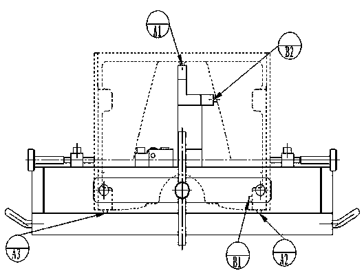
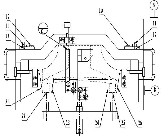
The invention relates to a low melting point alloy casting clamp for processing thin-walled parts, and a use method thereof. By adoption of the clamp, the rigidity during the processing of the parts can be increased, so that the parts are high in efficiency and stable in quality during cutting; the clamp is compact in structure, reliable in positioning, and convenient and fast in operation. According to the technical scheme, the clamp comprises a base; a sub-module I and a sub-module II are arranged on the upper surface of the base; an opening end of the sub-module I is opposite to the opening end of the sub-module II; a tight-propping block I is arranged on each of the upper surfaces of the two sides of the sub-module II; a tight-propping pin I perpendicular to the tight-propping block I is arranged on each tight-propping block I; a positioning I and a Z-shaped positioning support are arranged at the center of the upper surface of the sub-module II; a positioning II is arranged at the extending end of the upper surface of the positioning support; a tight-propping block II is arranged on the sub-module I; a tight-propping pin II, opposite to the positioning blocks I, is arranged on the tight-propping block II; a support seat is arranged on the other side of the sub-module II, and is connected with the sub-module II through a shaft; a rotating lever is arranged on the outer side of the shaft.
Description
technical field The invention relates to a low-melting-point alloy casting fixture for processing thin-walled parts and its application method. Background technique The components of aircraft engines require light weight, good strength and high precision. At present, most of the engine parts are made of high-temperature alloy materials, the wall thickness of the parts is getting thinner, and the manufacturing accuracy is within 0.01mm. Thin-walled parts are a very critical and important type of parts in aero-engine parts. The manufacturing workload of thin-walled parts accounts for about 10% of the manufacturing workload of the whole machine. Most of the thin-walled parts have complex and irregular shapes, which are very different from ordinary parts. In addition, the cutting performance of the material is poor, so it is a type of part that is difficult to process. Under the action of cutting force when thin-walled shell parts are processed, it is easy to cause thermal ...
Claims
Login to View More Application Information
Patent Timeline
 Patent Type & Authority Applications(China)
IPC IPC(8): B22D19/02B22D19/08B22D19/16
Inventor 张光伟董川赵养智魏广生
Owner 西安西航集团莱特航空制造技术有限公司
Features
- R&D
- Intellectual Property
- Life Sciences
- Materials
- Tech Scout
- Unparalleled Data Quality
- Higher Quality Content
- 60% Fewer Hallucinations
Learn More Browse by: Latest US Patents, China's latest patents, Technical Efficacy Thesaurus, Application Domain, Technology Topic, Popular Technical Reports.
© 2025 PatSnap. All rights reserved.Legal|Privacy policy|Modern Slavery Act Transparency Statement|Sitemap|About US| Contact US: help@patsnap.com


