Double-chamber fluidized bed sludge dryer

A sludge drying and fluidized bed technology, which is applied in the direction of dehydration/drying/concentrated sludge treatment, etc., can solve problems affecting the normal operation of fluidized bed dryers, and achieve the effect of ensuring normal operation

Active Publication Date: 2014-09-24
SOUTHEAST UNIV
View PDF5 Cites 6 Cited by
  • Summary
  • Abstract
  • Description
  • Claims
  • Application Information

AI Technical Summary

Problems solved by technology

[0003] Purpose of the invention: Aiming at the above-mentioned prior art, a double-chamber fluidized bed sludge dryer is proposed, which

Method used


Image

  • Double-chamber fluidized bed sludge dryer
  • Double-chamber fluidized bed sludge dryer
  • Double-chamber fluidized bed sludge dryer

Examples


Embodiment 1

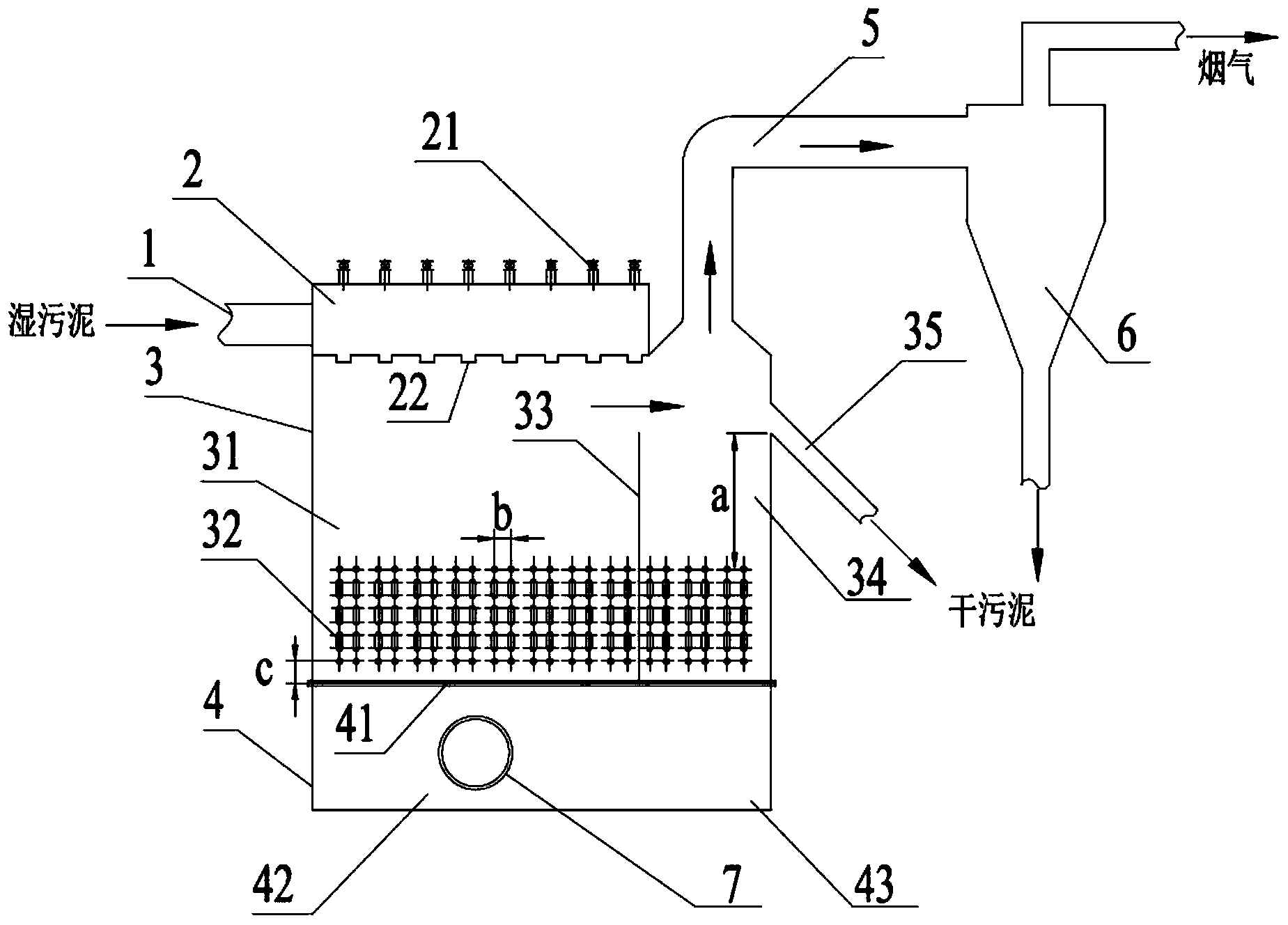
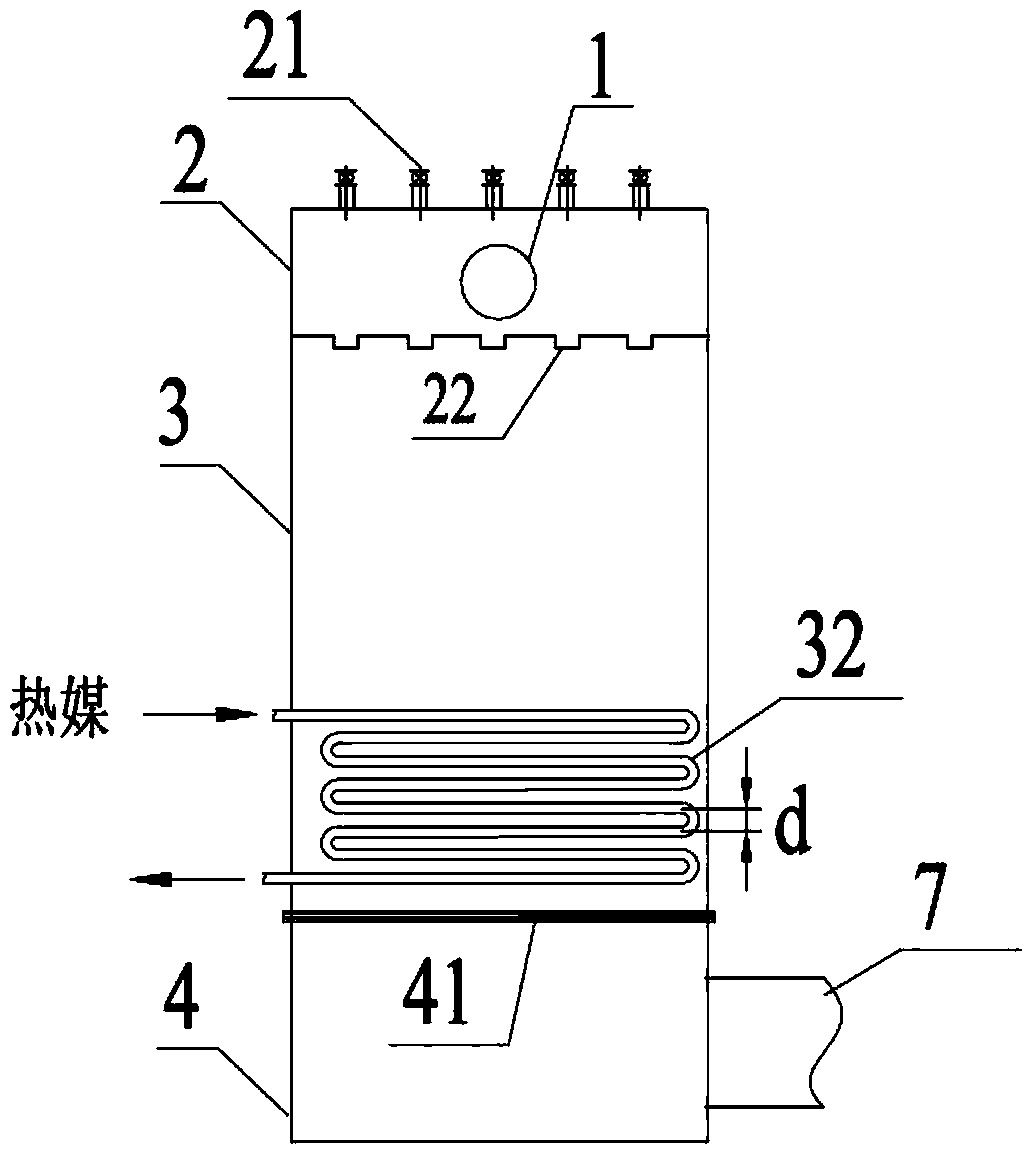
[0022] Embodiment 1: as figure 1 , figure 2 As shown, the double-chamber fluidized bed sludge dryer of the present invention is composed of a feed pipe 1, a distribution chamber 2, a drying chamber 3, an air chamber 4, an exhaust pipe 5, a cyclone separator 6, and an air inlet pipe 7. The distribution chamber 2 is arranged on the upper left side of the drying chamber 3, and the exhaust pipe 5 is arranged on the upper right side of the drying chamber 3; on the wall. The air chamber 4 is arranged directly below the drying chamber 3 , and the air chamber 4 is connected with the drying chamber 3 through an air distribution plate 41 . The cyclone separator 6 is arranged at the end of the exhaust pipe 5 , and the air inlet pipe 7 is connected to the air chamber 4 . Among them, several ball valves 21 are provided on the upper end surface of the distribution chamber 2, and one end of each ball valve 21 is connected to the distribution chamber 2, and several sludge nozzles 22 are p...

Embodiment 2

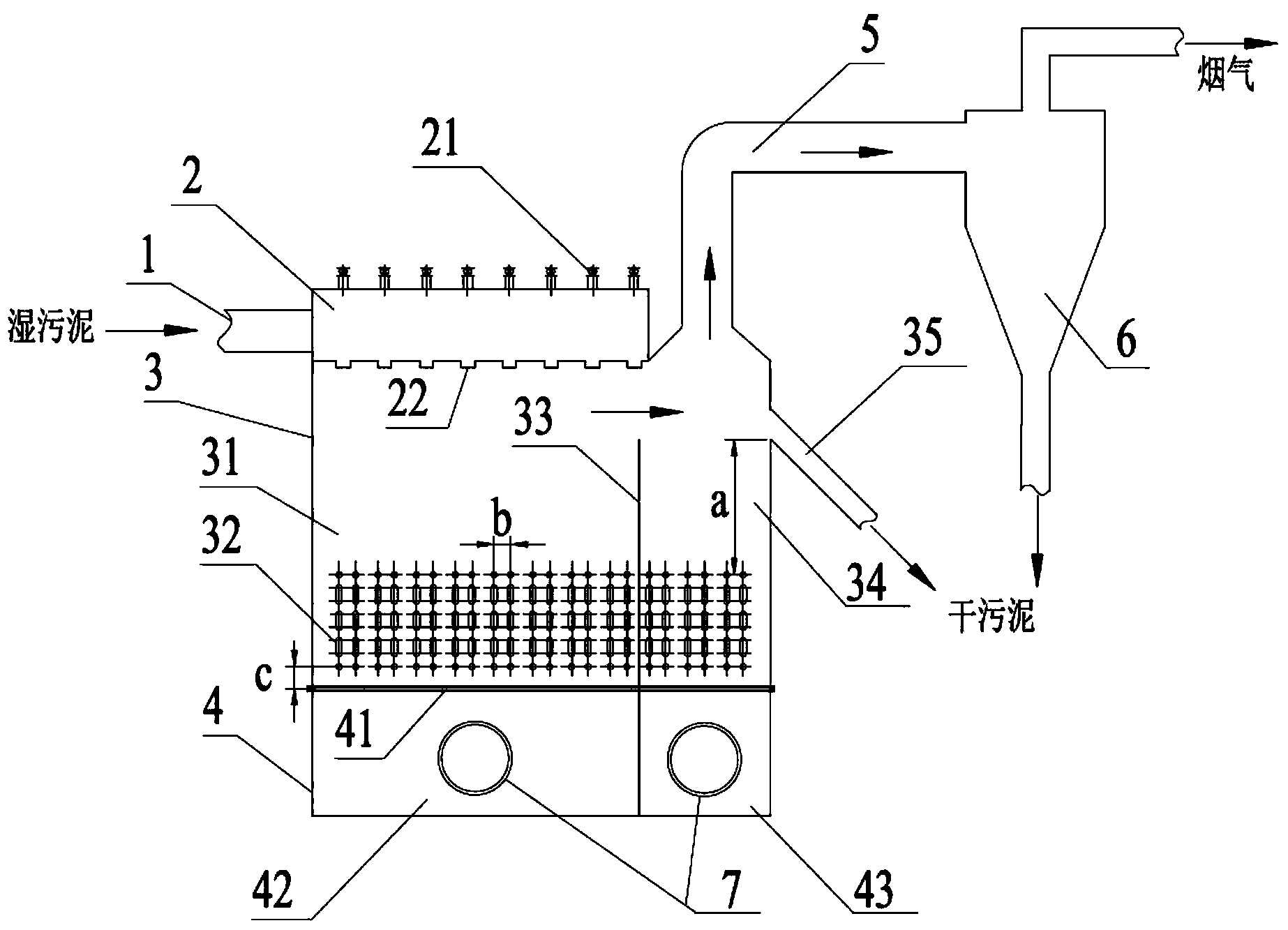
[0025] Embodiment 2: as image 3 As shown, the difference with Embodiment 1 is only: 1. The partition plate 33 divides the drying chamber 3 into a first sub-drying chamber 31 and a second sub-drying chamber 34 with a ratio of 3:1. In the first sub-drying chamber 31 Arrange 75% of the total heat exchanger area; 2. The air chamber 4 is also divided into the first sub-air chamber 41 and the second sub-air chamber 42 with a left-right ratio of 3:1 through the partition, and the two sub-air chambers are respectively connected through the air inlet pipe The independent air source of the wrist is set up to further control the ratio of the air intake of the two sub-drying chambers, and the first sub-drying chamber 31 is controlled to enter 75% of the total air volume to improve the drying efficiency; The fluidized bed drying chamber has the same structure.


PUM


Abstract

A double-chamber fluidized bed sludge dryer comprises a distribution chamber, an air chamber, a drying chamber, a cyclone separator and the like. The double-chamber fluidized bed sludge dryer is mainly characterized in that the side end surface of the distribution chamber is connected with a wet sludge feeding pipe, a plurality of ball valves are arranged on the upper end surface of the distribution chamber, a plurality of sludge spraying nozzles are arranged on the lower end surface of the distribution chamber, the centers of the ball valves coincide with the centers of the sludge spraying nozzles in the vertical direction, the air chamber and the drying chamber are respectively divided into two corresponding sub-chambers, the first air sub-chamber is filled with 67%-75% of total air, and 67%-75% of the total heat exchange surface of a heater is formed in the first drying sub-chamber. Under the condition that the work of the dryer is not influenced, the sludge spraying nozzles blocked by sundries like braided straps mixed in sludge can be quickly unblocked. In addition, the double-chamber fluidized bed sludge dryer has the advantages that feeding is uniform, dry sludge particulates are uniform in water content, the energy consumption is low, the drying efficiency is high, and operation is reliable.

Description

technical field [0001] The invention relates to a double-chamber fluidized bed sludge dryer, which belongs to the technical field of sludge drying. Background technique [0002] Sludge is the product of urban or industrial sewage treatment. About 70% of the pollutants in the sewage are transferred to the sludge, which contains toxic and harmful substances such as bacteria and heavy metals. If it is not treated properly, it will cause serious secondary pollution to the environment. Wet sludge has a high moisture content and is not easy to dehydrate. It must be dried before it can be burned stably. Ordinary mechanical drying methods have high energy consumption and low dehydration rate, which is difficult to meet industrial needs. Fluidized bed drying has the advantages of high dehydration rate and low unit energy consumption, and is gradually applied to wet sludge drying. However, the sludge contains sand, gravel, woven bags and other debris, which often block the sludge noz...

Claims


Application Information

Patent Timeline
IPC IPC(8): C02F11/16
Inventor 黄亚继邵志伟金保昇
Owner SOUTHEAST UNIV
Why Eureka
Try Eureka