
Floating type multi-floater wave power generation device

A power generation device and wave energy technology, applied in ocean energy power generation, engine components, machines/engines, etc., can solve the problems of many small waves, poor self-stability, and large volume, and achieve strong stability, high conversion efficiency, and reliability. high sex effect

Active Publication Date: 2014-09-24
STATE OCEAN TECH CENT
View PDF5 Cites 20 Cited by
  • Summary
  • Abstract
  • Description
  • Claims
  • Application Information

AI Technical Summary

Problems solved by technology

[0005] However, the wave energy generation devices with floating structures currently have the huge volume of the power generation device carrier and the capture structure, resulting in a large draft area of ​​the device, the carrier is significantly affected by wind and waves, and its own stability is poor, making the relative distance between the carrier and the capture structure The movement is not obvious, and the efficiency of wave energy absorption and utilization is low
The huge size of the capture structure will also lead to a slow response speed of the power generation device to the wave action, resulting in a phase difference between the motion of the capture structure and the waves, which will affect the wave energy absorption efficiency of the device
Moreover, due to the influence of terrain, the waves in my country's coastal waters are significantly broken, and there are many cases of small waves. Under the condition of small waves, the performance of wave energy devices with large carriers and capture structures is generally poor, and it is difficult to realize the industrialization of wave energy utilization.

Method used


Image

  • Floating type multi-floater wave power generation device
  • Floating type multi-floater wave power generation device
  • Floating type multi-floater wave power generation device

Examples


Embodiment Construction

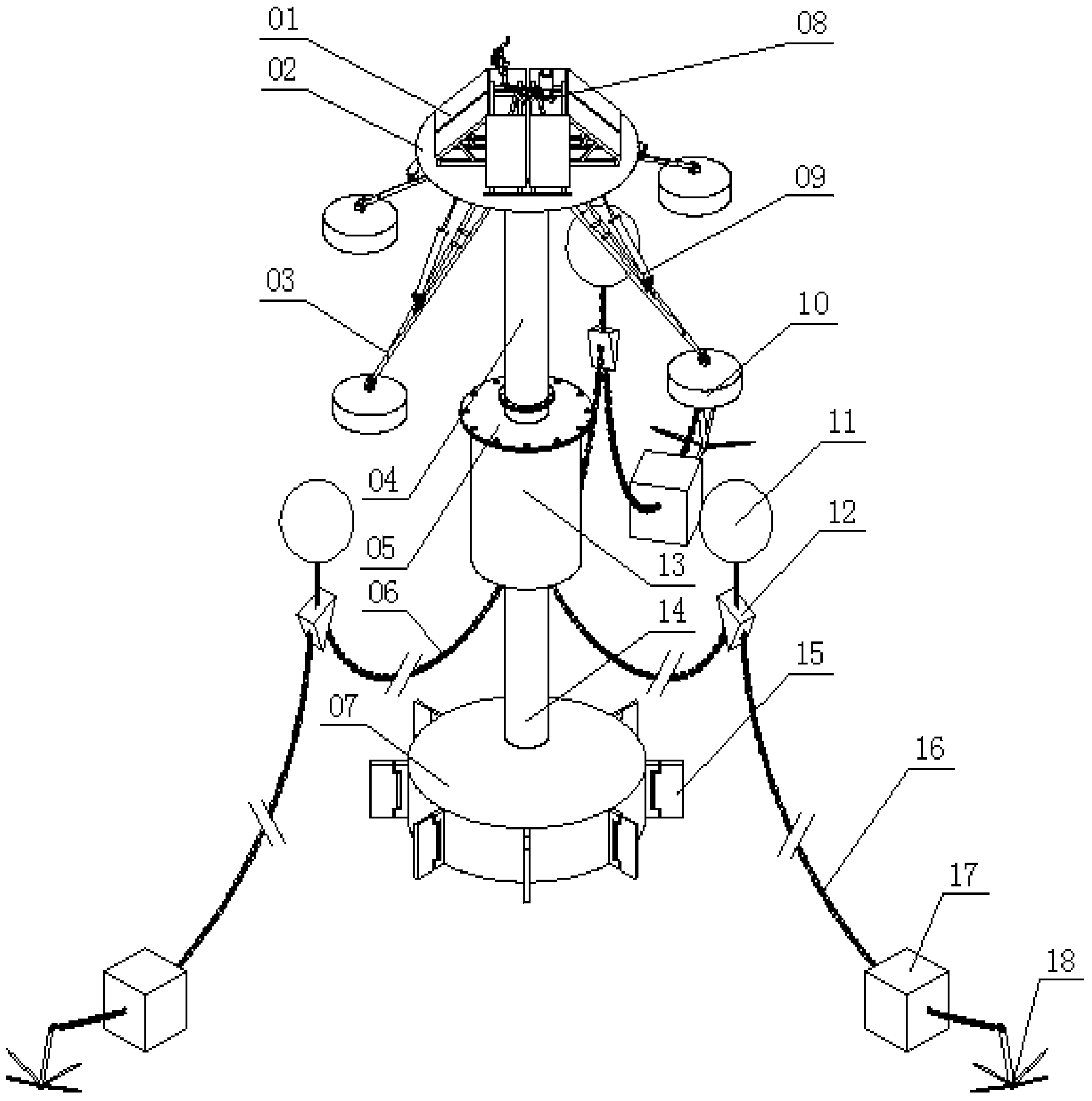
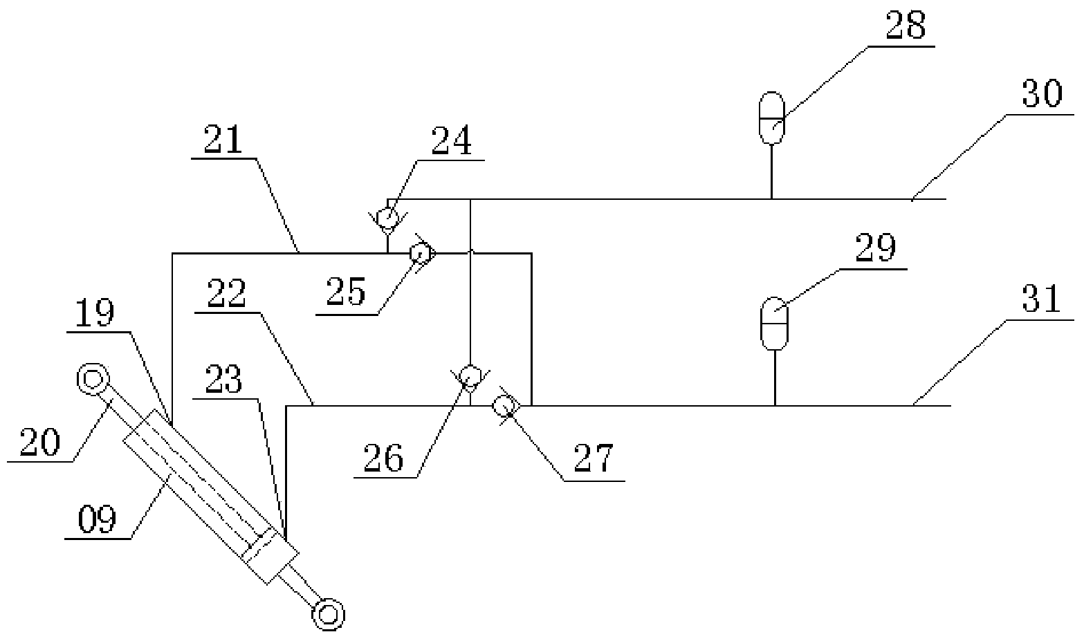
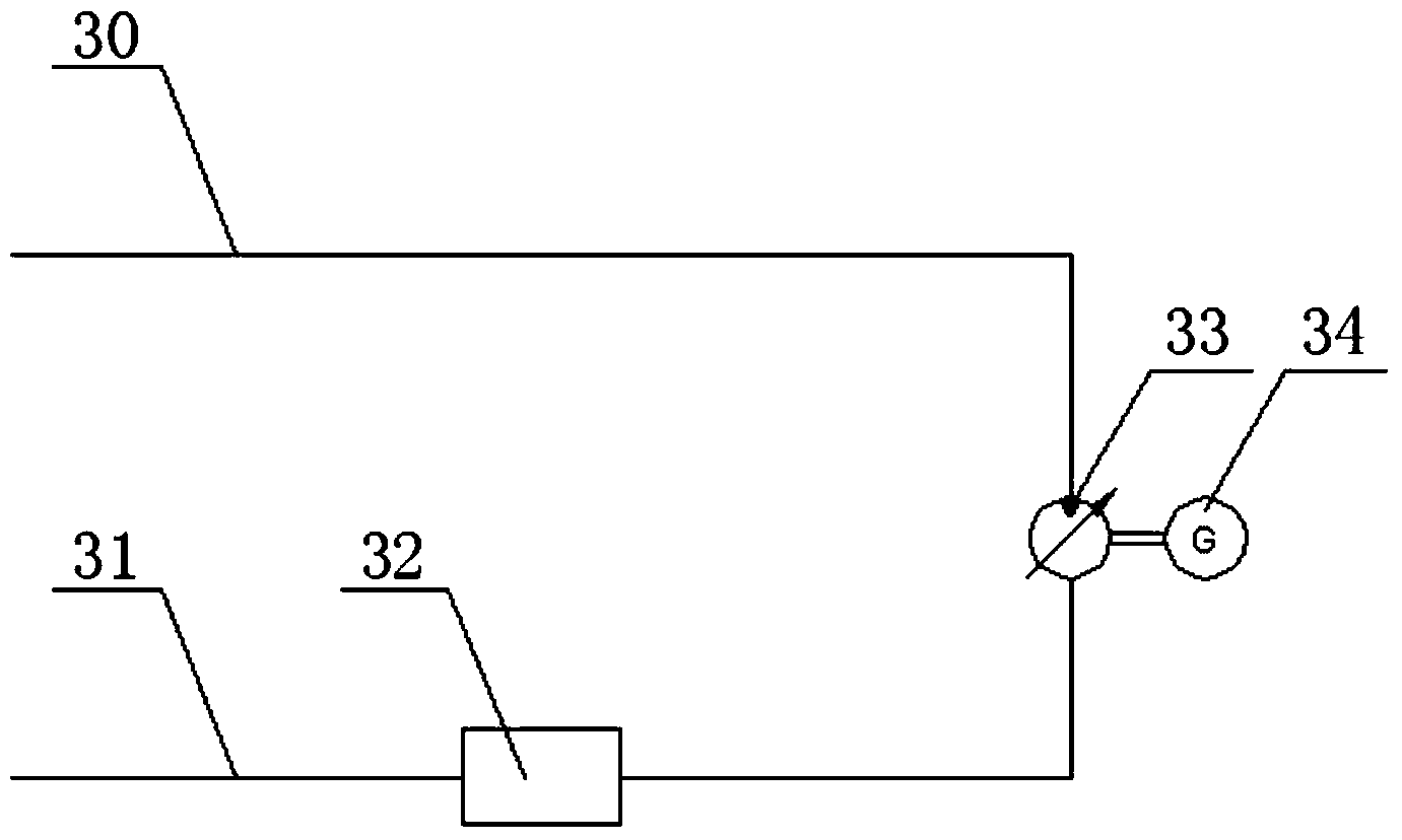
[0042] The technical scheme of the present invention will be further described in conjunction with the accompanying drawings, figure 1 It shows the basic structure of the floating multi-floor wave energy generation device, figure 2 with image 3 The basic structures of the hydraulic transmission system and the power generation system of the floating multi-floor wave energy generation device are shown respectively.

[0043] As shown in the figure, the floating multi-floor wave energy generating device includes a floating structure, an anchoring system, a hydraulic transmission system and a power generation system. The floating structure floats on the sea and is moored by the mooring system, and the hydraulic transmission system and power generation system are set together with the floating structure.

[0044] The floating structure includes a float 10, a main floating body and a swing arm 03, and the float 10 is respectively connected to the top of the main float by the swin...


PUM


Abstract

The invention discloses a floating type multi-floater wave power generation device which comprises a floating type structure, a mooring system, a hydraulic transmission system and a power generation system. The floating type structure floats on the sea surface and is moored through the mooring system. Multiple floaters of the floating type structure are connected with a main floating body through swing arms respectively. The floaters move along with waves and resonate together with waves, the floaters which do the floating and sinking movement after being excited by waves drive the swing arms to swing around a fixed fulcrum, a piston rod of a hydraulic cylinder is driven to reciprocate, an oily medium in the hydraulic cylinder is pushed to enter a hydraulic system to form a circuit and to enter a hydraulic motor, the hydraulic motor rotates to drive an electric generator to generate electricity, and then power generation is achieved through wave energy. According to the floating type multi-floater wave power generation device, the multiple floaters which move up and down along with waves absorb sea wave energy, stability of the main floating body of the device in waves is improved through a damping type base plate and the mooring system which adopts the three-point horizontal mooring method, and the floating type multi-floater wave power generation device has the advantages of being high in conversion efficiency, stability and reliability.

Description

technical field [0001] The invention relates to an ocean wave energy generating device, in particular to a floating multi-floor wave energy generating device. Background technique [0002] With the depletion of fossil energy such as coal and oil, the development and utilization of various new forms of renewable energy has become the focus of common attention of all countries in the world. Ocean energy represented by wave energy has the characteristics of huge reserves, clean and renewable, and is an alternative energy form with great development potential. The development and utilization of wave energy has been valued by the European North Sea coastal countries since the outbreak of the world oil crisis in the 1970s. After more than 30 years of intensive investment and continuous development, great progress has been made. [0003] Most of the early wave energy power generation devices were shore-based fixed structures, and the wave energy devices were installed on fixed hyd...

Claims


Application Information

Patent Timeline
IPC IPC(8): F03B13/14
CPCY02E10/38Y02E10/30
Inventor 崔琳李蒙张原飞黄勇薛彩霞王锰段云棋
Owner STATE OCEAN TECH CENT
Learn More