
Mobile phone spectrograph module and mobile phone spectrograph with mobile phone spectrograph module

A spectrometer and mobile phone technology, applied in the field of spectrometers, can solve the problems of scattered light positions, difficult design, and inability to focus, etc., and achieve the effects of easy installation and expansion of peripherals, simple and square shape and structure, and good spectral resolution

Active Publication Date: 2014-09-24
SHENZHEN INST OF ADVANCED TECH
View PDF11 Cites 24 Cited by
  • Summary
  • Abstract
  • Description
  • Claims
  • Application Information

AI Technical Summary

Problems solved by technology

[0005] First, the spectral resolution is not ideal
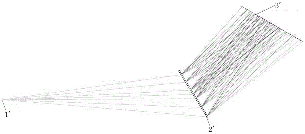
In the optical path, the polychromatic light passes through the slit and directly irradiates the grating. These light rays are not parallel light, but divergent light. After being diffracted by the plane transmission grating, it is difficult to focus and image in a short distance, and the spectral resolution is not ideal.
from figure 1 It can be seen from the ray tracing simulation that the light positions of each wavelength on the receiving surface of the mobile phone lens are scattered and cannot be focused, which means that the spectra captured by the CMOS detector of the mobile phone are seriously overlapped and the spectral resolution is poor.
Prolonging the imaging distance (the distance from the grating to the receiving surface of the mobile phone lens) can slightly improve the focusing of the light, but the elongation of the imaging distance will significantly increase the size of the optical-mechanical module, and the portability will deteriorate.
[0006] Second, the structure is not optimized enough
Such an irregular shape will bring certain difficulties to the design when expanding peripherals for absorption and reflection spectrum testing

Method used


Image

  • Mobile phone spectrograph module and mobile phone spectrograph with mobile phone spectrograph module
  • Mobile phone spectrograph module and mobile phone spectrograph with mobile phone spectrograph module
  • Mobile phone spectrograph module and mobile phone spectrograph with mobile phone spectrograph module

Examples


Embodiment Construction

[0024] In order to make the object, technical solution and advantages of the present invention clearer, the present invention will be further described in detail below in conjunction with the accompanying drawings and embodiments. It should be understood that the specific embodiments described here are only used to explain the present invention, not to limit the present invention.

[0025] It should be noted that when an element is referred to as being “fixed on” or “disposed on” another element, it may be directly on the other element or there may be an intervening element at the same time. When an element is referred to as being "connected to" another element, it can be directly connected to the other element or intervening elements may also be present.

[0026] It should also be noted that the orientation terms such as left, right, up, and down in this embodiment are only relative concepts or refer to the normal use state of the product, and should not be regarded as limiti...


PUM


Abstract

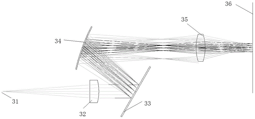
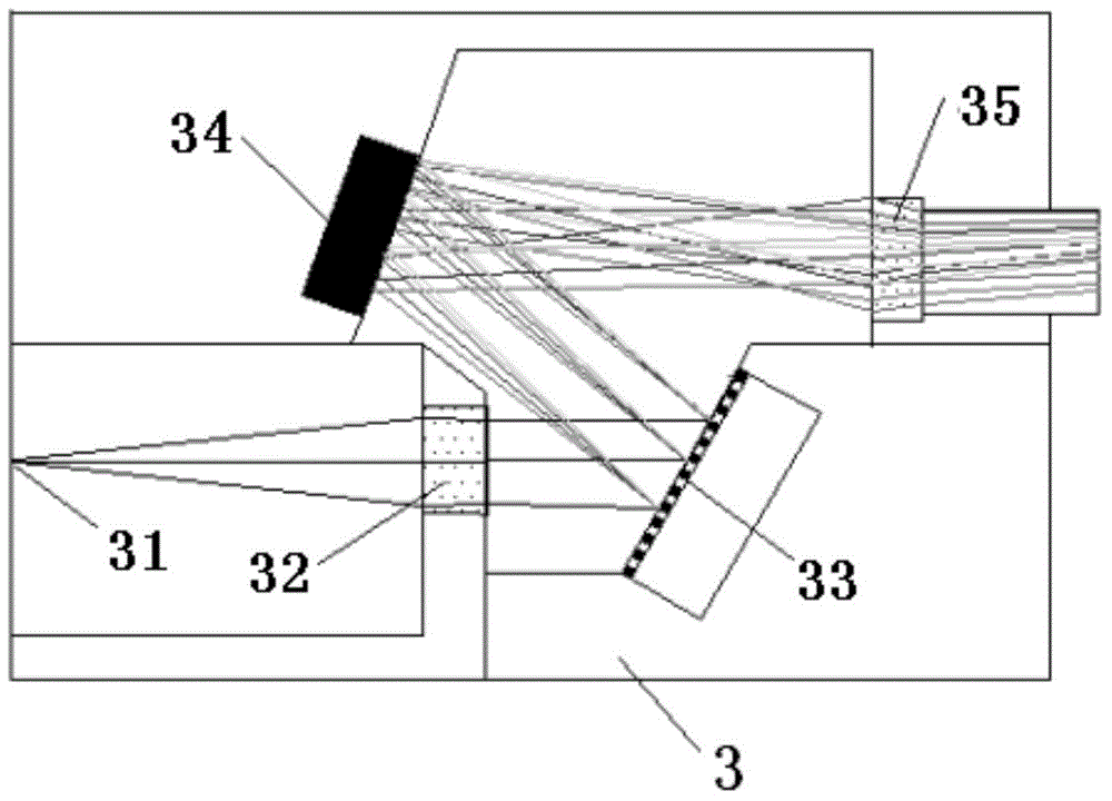
The invention is suitable for the technical field of spectrographs, and discloses a mobile phone spectrograph module and a mobile phone spectrograph with the mobile phone spectrograph module. The mobile phone spectrograph module comprises a shell with a slit. A plane-convex collimating lens used for collimating light rays entering the slit is arranged in the shell. A reflecting grating used for reflecting the light rays collimated by the plane-convex collimating lens and changing the incident polychromatic light into monochromatic light emitted in different directions is arranged on one side of the plane-convex collimating lens. A spherical reflecting mirror used for gathering the monochromatic light emitted by the reflecting grating is further arranged in the shell. A biconvex lens is arranged between the spherical reflecting mirror and the receiving face of a mobile phone camera. The mobile phone spectrograph comprises a mobile phone and the mobile phone spectrograph module. The mobile phone spectrograph module and the mobile phone spectrograph with the mobile phone spectrograph module are high in spectral resolution, compact in structure, easy to install and capable of being easily expanded and externally arranged.

Description

technical field [0001] The invention belongs to the technical field of spectrometers, and in particular relates to a mobile phone spectrometer module and a mobile phone spectrometer with the mobile phone spectrometer module. Background technique [0002] Spectrometer is an important tool in food testing, environmental monitoring, biochemical analysis, lighting testing and other fields. With the increasing demand for daily and real-time detection, spectrometers have gradually moved out of the laboratory in the past two decades, and are developing towards the trend of miniaturization. At present, the mainstream miniature spectrometers are represented by the products of American Ocean Optics, Holland Avantis, Japan Hamamatsu and other companies. Most of them are based on Cheney-Turner optical path or flat-field concave grating optical path, and adopt CCD / CMOS linear array detector to receive spectrum. , Spectral data is transmitted to a computer or embedded industrial computer...

Claims


Application Information

Patent Timeline
Patent Type & Authority Applications(China)
IPC IPC(8): G01J3/28
Inventor 林慧张国栋
Owner SHENZHEN INST OF ADVANCED TECH
Learn More