Concrete carbonized protective layer bonding strength detector

A technology of bonding strength and protective layer, which is applied in the field of testing devices for the bonding strength of the protective layer, can solve the problems of large error in test results, complicated operation, and inability to apply on-site detection, etc., and achieves small error in test results, convenient operation, and excellent structure simple effect

Active Publication Date: 2014-09-24
ANHUI & HUAI RIVER WATER RESOURCES RES INST
View PDF9 Cites 6 Cited by
  • Summary
  • Abstract
  • Description
  • Claims
  • Application Information

AI Technical Summary

Problems solved by technology

[0003] The purpose of the present invention is to provide a method for testing the adhesion of coating film in view of some problems existing in the current detection of the bond strength between the protective co

Method used


Image

  • Concrete carbonized protective layer bonding strength detector

Examples


Embodiment Construction

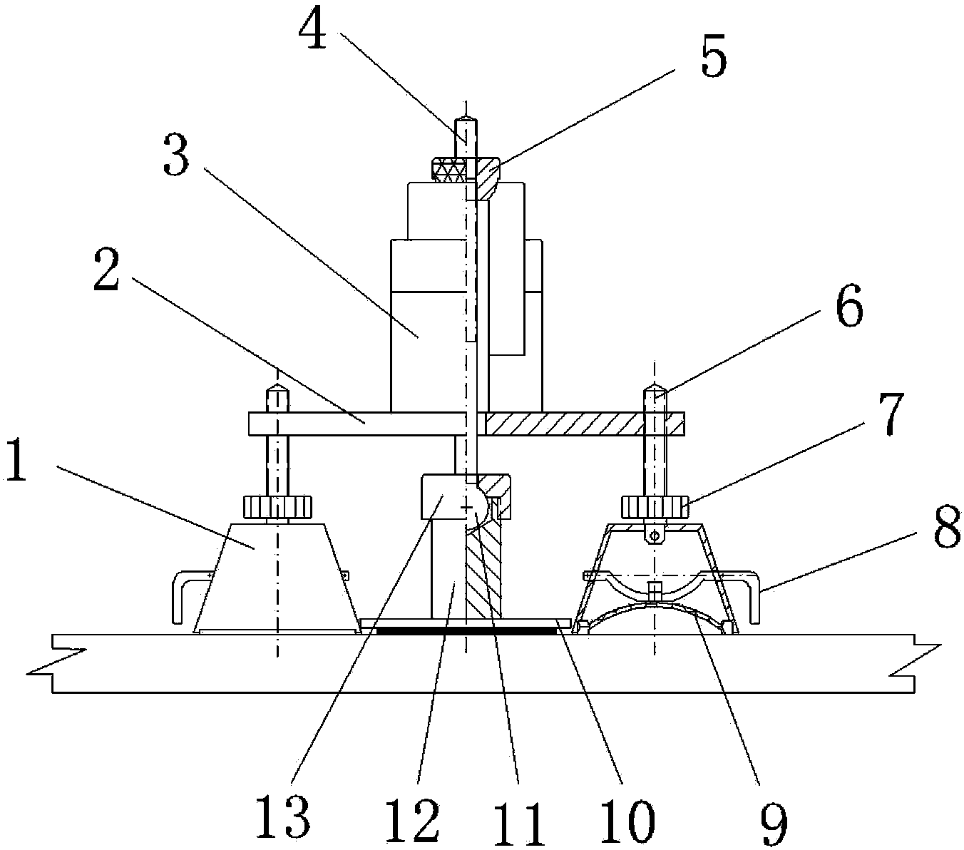
[0011] Such as figure 1 As shown, the concrete carbonization protective layer bond strength tester includes: a platen 2, a lifter 3 is provided in the middle of the plane on the platen, a matching lifting screw 4 is provided on the lifter, and an adjusting screw is provided on the upper side of the lifting screw. Nut 5, the adjusting nut cooperates with the upper end of the lifter, the lower end of the lifting screw 4 is provided with a ball head 11, the bottom of the platen is provided with an adhesion plate 10, and the adhesion plate 10 is provided with a matching ball head seat 12 and a gland nut 13 , the ball head 11 cooperates with the ball head seat and the gland nut respectively, a group of adjusting screw rods 6 are arranged on the periphery of the platen 2, an integral handwheel 7 is arranged on the lower side of the adjusting screw rod, and a supporting foot is arranged at the lower end of the adjusting screw rod 1. The shape of the supporting foot is a conical barre...


PUM


Abstract

The invention relates to a concrete carbonized protective layer bonding strength detector. The concrete carbonized protective layer bonding strength detector comprises a table board (2). A lifter (3) is arranged on the table board. A lifting threaded rod (4) is arranged on the lifter in a matched mode. An adhesion plate (10) is arranged below the table board. The lifting threaded rod penetrates through the table board and is matched with the adhesion plate. The periphery of the table board (2) is provided with a set of adjusting threaded rods (6). The lower end of each adjusting threaded rod is provided with a supporting leg (1) in a rotating fit mode. The bottom of each supporting leg (1) is provided with a suction cup (9). By the adoption of the technical scheme, the concrete carbonized protective layer bonding strength detector has the advantages of being simple in structure, convenient to operate, small in testing result error, applicable to a construction site and the like.

Description

Technical field: [0001] The invention relates to a test device for the bond strength of a protective layer, in particular to a detector for the bond strength of a concrete carbonized protective layer. Background technique: [0002] After hydraulic structures are put into operation, different phenomena of aging and disease will inevitably appear. For example, 10 years after the sluice is built, the concrete of the gate piers, working bridges, pedestrian bridges and other parts will be obviously carbonized, and the pedestrian bridge slab may have steel rust expansion joints due to the thin protective layer of steel bars. The most widely used treatment method at this stage is to apply protective materials on the concrete surface, such as SBR mortar or protective coatings such as epoxy coatings and chlorosulfonated polyethylene coatings. The quality of the coating is finally reflected in the coating film. Therefore, the quality inspection after painting is mainly to detect the ...

Claims


Application Information

Patent Timeline
IPC IPC(8): G01N19/04
Inventor 张今阳邰洪生程海英薛亚锋陈勇唐开红罗居刚徐善杰张青松
Owner ANHUI & HUAI RIVER WATER RESOURCES RES INST
Why Eureka
Try Eureka