Light shift elimination method for SERF atomic spin magnetometers

A technology of atomic spin and optical displacement, applied in the size/direction of magnetic field, magnetic field measurement using magneto-optical equipment, stray field compensation, etc. It can reduce the error and improve the sensitivity of the SERF atomic spin magnetometer.

Active Publication Date: 2014-09-24
SOUTHEAST UNIV
View PDF7 Cites 21 Cited by
  • Summary
  • Abstract
  • Description
  • Claims
  • Application Information

AI Technical Summary

Problems solved by technology

Due to the instability of the pumping laser, the optical power and frequency fluctuate, and the optical displacement will output these fluctuations in the form of noise, which becomes one of the important sources of error in the pumping optical system, which greatly limits the sensitivity of the SERF atomic spin magnetometer.
[0006] Optical displacement commonly exists in atomic devices, such as atomic clocks, atomic frequency standards, etc. At present, foreign scholars have proposed many effective optical displacement elimination methods for the above two ato

Method used


Image

  • Light shift elimination method for SERF atomic spin magnetometers
  • Light shift elimination method for SERF atomic spin magnetometers
  • Light shift elimination method for SERF atomic spin magnetometers

Examples


Embodiment Construction

[0026] Below in conjunction with accompanying drawing and specific embodiment, further illustrate the present invention, should be understood that these embodiments are only for illustrating the present invention and are not intended to limit the scope of the present invention, after having read the present invention, those skilled in the art will understand various aspects of the present invention Modifications in equivalent forms all fall within the scope defined by the appended claims of this application.

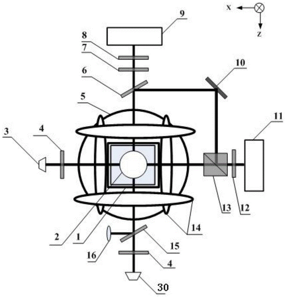
[0027] Such as figure 1 Shown, the present invention comprises the following steps:

[0028] 1) Optical path adjustment. figure 1 , the pump laser 9 located on the z axis emits cesium atoms D 1 line (894nm), that is, the pumping light; the detection laser 11 located on the x-axis emits cesium atoms D 2 Line (852nm), that is, the detection light. The pump light passes through the first polarizer 8 and The wave plate 7 becomes circularly polarized light and propagate...


PUM

PropertyMeasurementUnit
Wavelengthaaaaaaaaaa

Abstract

The invention discloses a light shift elimination method for SERF atomic spin magnetometers; the light shift measurement and elimination method based on the dichroism principle is provided aiming at the problem that sensitivity of the SERF atomic spin magnetometer in measurement may be influence by light shift. According to the light shift elimination method, the deficiency of lack of effective light shift measurement, monitoring and elimination methods is made up, and meanwhile improvement on sensitivity of the SERF atomic spin magnetometer is guaranteed.

Description

technical field [0001] The invention relates to a method for eliminating optical displacement of a SERF atomic spin magnetometer, which belongs to the technical field of optical detection and weak magnetic detection. Background technique [0002] The SERF atomic spin magnetometer (hereinafter referred to as the atomic magnetometer) has become a project developed by foreign military powers because of its ultra-high theoretical sensitivity. The atomic magnetometer is a magnetic field measurement device based on ultra-fine energy level atomic transitions and works in a weak magnetic environment. It mainly includes: pumping optical system, detection optical system, magnetic field shielding and magnetic field compensation system, non-magnetic electric heating systems and alkali metal gas chambers, etc. [0003] Under the action of light and external magnetic field, the Zeeman effect (Zeeman effect) and Stark effect (Stark effect) will occur in the atomic energy level, so that it...

Claims


Application Information

Patent Timeline
IPC IPC(8): G01R33/032G01R33/025
Inventor 陈熙源张红邹升
Owner SOUTHEAST UNIV
Why Eureka
Try Eureka