Microstructure of four-cilium bionic MEMS vector acoustic sensor

An underwater acoustic sensor and microstructure technology, applied in the direction of microstructure technology, microstructure device, microstructure device composed of deformable elements, etc., can solve the sensitivity and frequency response range affecting the engineering application of MEMS hydrophone, Sensitivity and frequency response range conflict, reducing the resolution of vector hydrophones, etc., to achieve the effect of reducing frequency response range, improving sensitivity, and wide application range

Inactive Publication Date: 2014-09-24
苏州中盛纳米科技有限公司
View PDF5 Cites 25 Cited by
  • Summary
  • Abstract
  • Description
  • Claims
  • Application Information

AI Technical Summary

Problems solved by technology

However, there has always been a contradiction between the sensitivity and the frequency response range of the hydrophone, that is, if the frequency response range is to be wider, the sensitivity of the hydrophone must be reduced, thereby reducing the resolution of the vector hydrophone; if the sensitivity is to be increased, It is necessary to reduce the frequency range of the hydrophone
However, in practical engineering applications, the hydrophone needs to have a certain frequency response range, so the contradiction between the sensitivity and the frequency response range directly affects the further engineering application of the MEMS hydrophone
Another example is that the public document with the patent application number 201210557743.X proposes a microstructure of a quaternary array MEMS vector hydrophone, which can effectively eliminate the blurring problem of starboard and starboard sides, but there is still a gap between the above-mentioned sensitivity and frequency response range. contradictory shortcomings

Method used


Image

  • Microstructure of four-cilium bionic MEMS vector acoustic sensor
  • Microstructure of four-cilium bionic MEMS vector acoustic sensor
  • Microstructure of four-cilium bionic MEMS vector acoustic sensor

Examples


Embodiment Construction

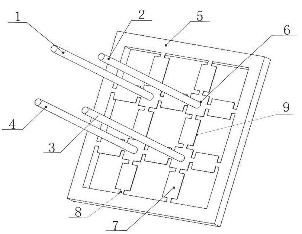
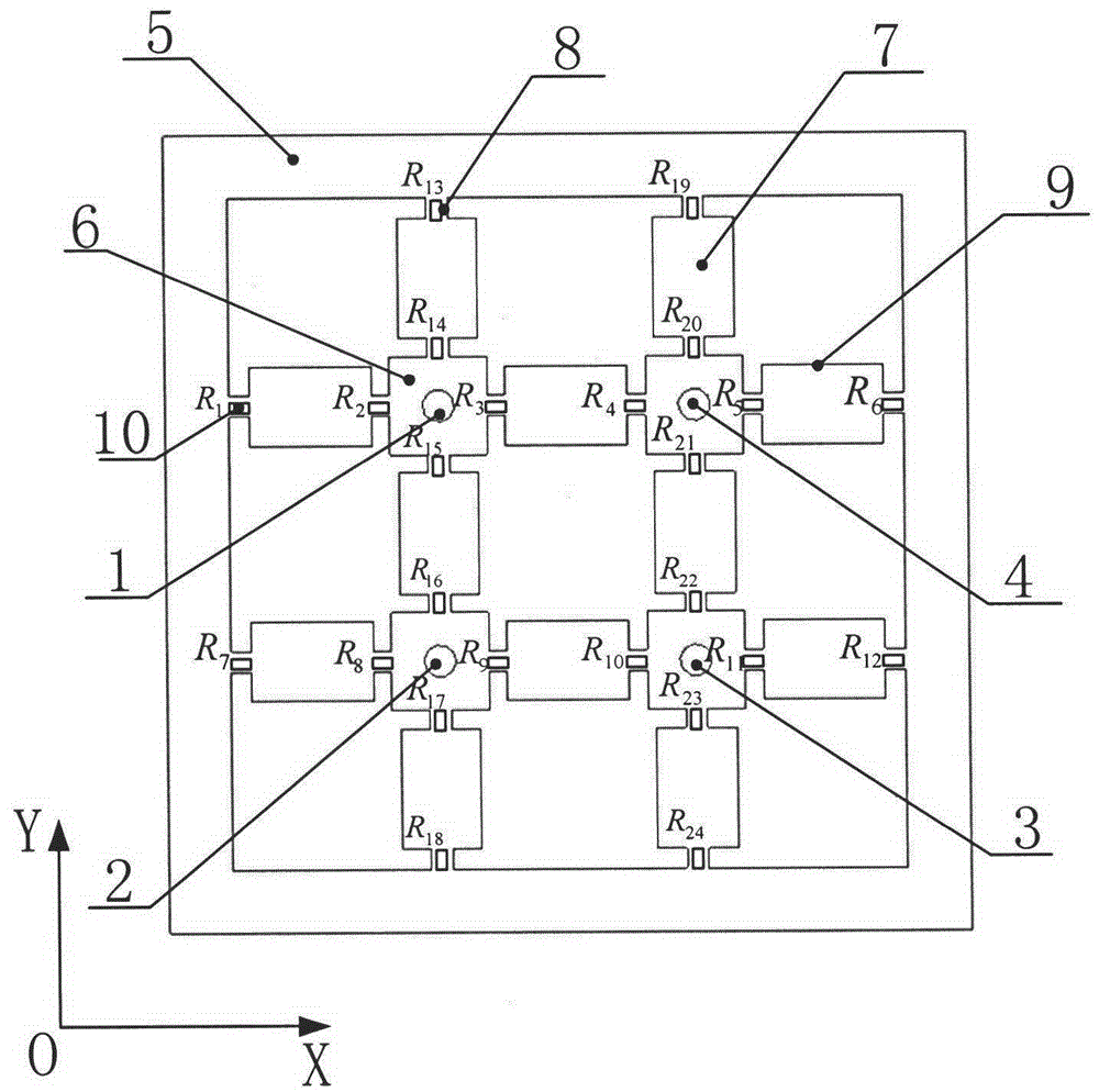
[0029] Such as figure 1 As shown, a four-cilia bionic MEMS vector underwater acoustic sensor microstructure, including a square frame 5 obtained by MEMS micromachining technology, a "well" shaped cantilever arm 9 and vertical cilia erected in the center of the square frame 5, in the In some illustrative embodiments, the vertical cilia are made of a material with a density close to that of water. Each section beam of the "well" shaped cantilever arm 9 is composed of a wide section 7 and a narrow section 8, and the narrow section 8 is symmetrically arranged on both sides of the wide section 7, that is, the "well" shaped cantilever beam Each section of the beam 9 is designed in a narrow-wide-narrow manner, and the beams of each section are connected by a square connecting body 6 located at the intersection of the "well"-shaped cantilever arms 9 . The sensor microstructure also includes vertical cilia 1 , vertical cilia 2 , vertical cilia 3 and vertical cilia 4 fixed vertically ...


PUM


Abstract

The invention discloses a microstructure of a four-cilium bionic MEMS vector acoustic sensor. The microstructure comprises a square frame and a #-shaped suspension beam arm erected at the centre of the square frame, whereon each section of the beam of the #-shaped suspension beam arm is composed of a wide section and narrow sections which are symmetrically arranged at the both sides of the wide section; piezoresistors with the same resistance are arranged on the narrow sections respectively; the piezoresistors form two groups of Wheatstone full bridges; the two groups of Wheatstone full bridges are used for measuring aquatic signals in two mutually vertical directions respectively; vertical cilia are fixedly arranged on each square connection body. According to the microstructure disclosed by the invention, four bionic cilia are integrated on one chip by virtue of an MEMS technology, and the #-shaped suspension beam arm structure is adopted, and local stress concentration is improved in the narrow-wide-narrow form of each section of the beam, thus improving the resistance changes of the piezoresistors, and then improving the sensitivity of the structure; therefore, the contradiction between the sensitivity and the frequency response range of the existing MEMS bionic hydrophone is solved.

Description

technical field [0001] The invention belongs to the field of vector hydrophones, in particular to a four-cilia bionic MEMS two-dimensional vector hydrophone microstructure with multi-segment beams. Background technique [0002] In view of the micro-electro-mechanical system (MEMS, Micro Electro Mechanical System) technology has the characteristics of miniaturization, diversification, micro-electronics and the advantages of easy realization of the miniaturization and consistency of underwater acoustic sensors, MEMS vector hydrophones have become the current domestic It is one of the hotspots in the field of external sound transducer research. The public document with the patent application number 200610012991.0 proposes a resonant tunneling bionic vector underwater acoustic sensor, which uses a single sensor to detect the orientation of the underwater acoustic signal in a two-dimensional plane, although it breaks through the sensitivity and Limit state of resolution. Howeve...

Claims


Application Information

Patent Timeline
Patent Type & Authority Applications(China)
IPC IPC(8): G01S5/20B81B3/00
CPCB81B3/0072G01H3/00
Inventor 张国军丑修建刘俊
Owner 苏州中盛纳米科技有限公司
Why Eureka
Try Eureka