
Sealing glass geometries for sensitivity enhancement of thick-film piezoresistive pressure sensors

a piezoresistive pressure sensor and thick film technology, applied in the field of sealing glass geometries for thick-film piezoresistive pressure sensors, can solve the problems of insufficient gain of application-specific integrated circuits (asic), and the limited sensitivity of most current pressure sensors used in air conditioning systems, so as to improve the effect of performance, increase the resistance of the change of resistors, and significant enhancement of wheatstone bridge resistor strain

Active Publication Date: 2021-02-11
VITESCO TECH USA LLC
View PDF0 Cites 0 Cited by
  • Summary
  • Abstract
  • Description
  • Claims
  • Application Information

AI Technical Summary

Benefits of technology

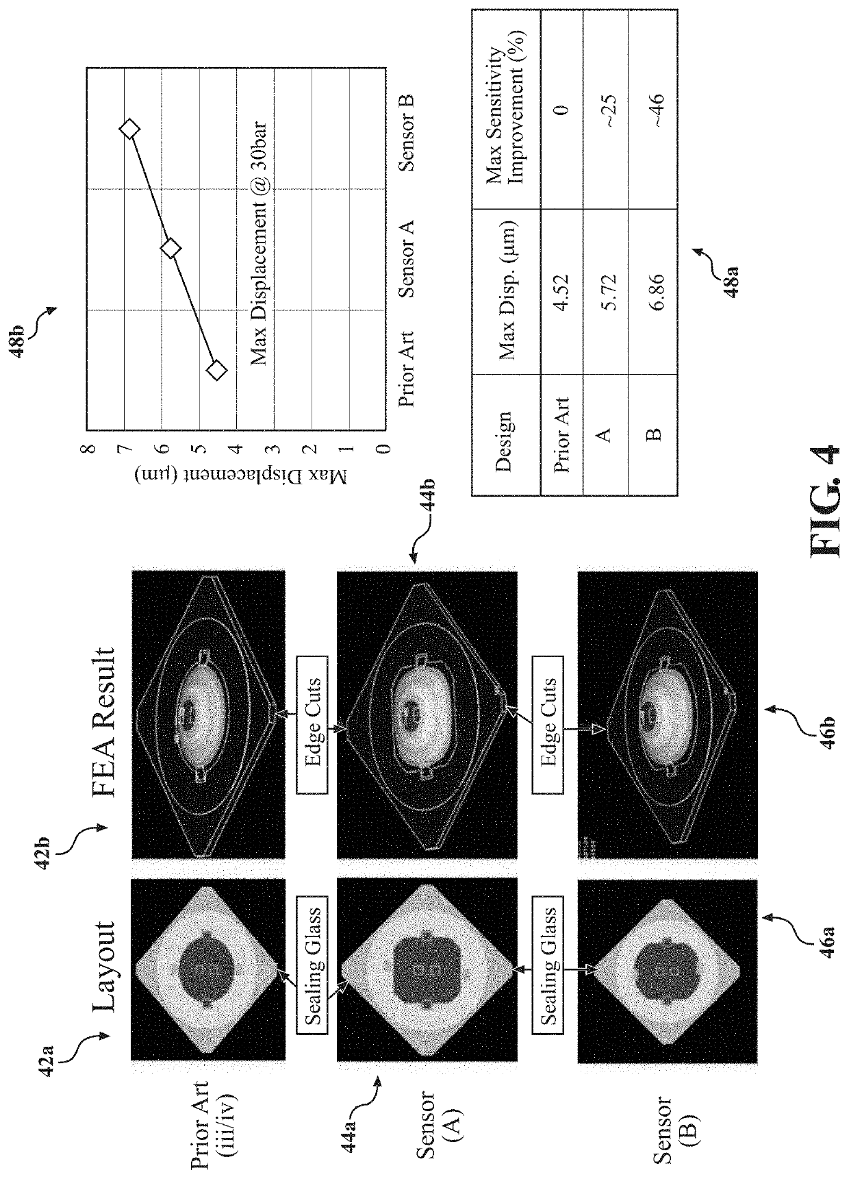
The present invention is a pressure sensor assembly that improves performance by tailoring sealing glass geometry to control the deformation of the diaphragm and enhance the strain of the Wheatstone bridge resistors. This increases the sensitivity of the circuit, resulting in higher output. The unique shapes of the layer of sealing glass accommodate other features like an NTC thermistor contact area, while reducing the cost by allowing for smaller size of the piezoresistors. The pressure sensor assembly includes a pressure sensing element, plurality of piezoresistors, and at least one layer of sealing glass connected to the diaphragm, which maximizes the sensitivity of the plurality of piezoresistors.

Problems solved by technology

Most current pressure sensors used in air conditioning systems have piezoresistors with limited sensitivity.
Additionally, the Application-Specific Integrated Circuit (ASIC) gain is too high because of the low sensitivity of the current designs of piezoresistor-cell sensing elements of thick-film resistors on ceramic diaphragms.

Method used


Image

  • Sealing glass geometries for sensitivity enhancement of thick-film piezoresistive pressure sensors
  • Sealing glass geometries for sensitivity enhancement of thick-film piezoresistive pressure sensors
  • Sealing glass geometries for sensitivity enhancement of thick-film piezoresistive pressure sensors

Examples


first embodiment

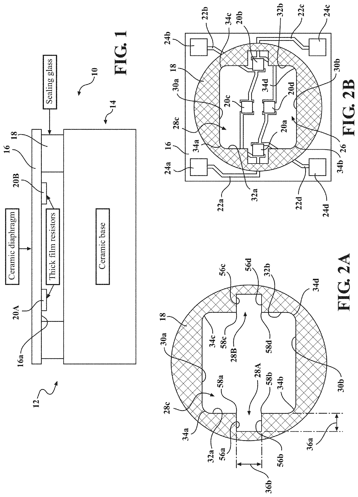
[0034]An example of the pressure sensor assembly according to the present invention is shown in FIGS. 1-2B generally at 10. The sensor 10 includes a pressure sensing element, shown generally at 12, and a base, which in this embodiment is a ceramic base, shown generally at 14. The pressure sensing element 12 includes a diaphragm, which in this embodiment is a ceramic diaphragm 16, which is supported on a layer of sealing glass 18. Referring to FIG. 2B, attached to a first side 16a of the diaphragm 16 is a plurality of thick-film piezoresistors 20a-20d, and each of the piezoresistors 20a-20d is connected to and in electrical communication with one or more of a plurality of conductive traces 22a-22d, and each of the conductive traces 22a-22d is connected to and in electrical communication with one of a plurality of bond pads 24a-24d. The conductive traces 22a-22d and the bond pads 24a-24d are also connected to the first side 16a of the diaphragm 16. The piezoresistors 20a-20d, the cond...

third embodiment

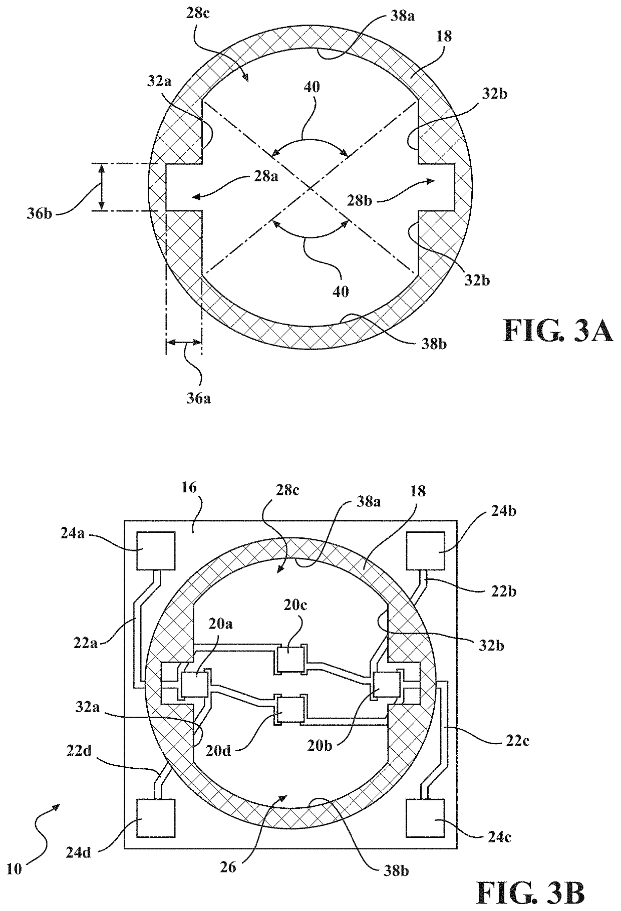
[0042]the pressure sensor 10 according to the present invention is shown in FIGS. 5A-5B, with like numbers referring to like elements. In this embodiment, the layer of sealing glass 18 is similar to the first embodiment, but in this embodiment the layer of sealing glass 18 does not have the arc portions 34a-34d. Rather, the first end of the first inner surface 30a terminates into the first side surface 32a, and the second end of the first inner surface 30a terminates into the second side surface 32b. Furthermore, the first end of the second inner surface 30b terminates into the second side surface 32b, and the second end of the second inner surface 30b terminates into the first side surface 32a.

fourth embodiment

[0043]the pressure sensor 10 according to the present invention is shown in FIGS. 6A-6B, with like numbers referring to like elements. In this embodiment, the layer of sealing glass 18 includes the inner surfaces 30a,30b and the side surfaces 32a,32b, but does not include the arc portions 34a-34d. Also, in the previous embodiments, the outer perimeter surface 18a of the layer of sealing glass 18 is substantially circular, however in this embodiment, the layer of sealing glass 18 has a multi-sided perimeter 50. In this embodiment, the multi-sided perimeter 50 has twenty-four flat surfaces. However, it is within the scope of the invention that the multi-sided perimeter may include more or less flat surfaces. It is also within the scope of the invention that the outer perimeter surface 18a may also include other shapes which may be curved or flat, to facilitate the sensor 10 meeting various packaging requirements, and signal routing requirements.

[0044]It should be noted that in the emb...


PUM

PropertyMeasurementUnit
angleaaaaaaaaaa
pressureaaaaaaaaaa
pressureaaaaaaaaaa

Abstract

A pressure sensor assembly, which includes a pressure sensing element having a diaphragm, a plurality of piezoresistors connected to the diaphragm, and at least one layer of sealing glass connected to the diaphragm. The pressure sensor assembly also includes a base, a layer of sealing glass is connected to the base, and is configured to maximize the sensitivity of the plurality of piezoresistors via tailoring the side surfaces of the glass surface to control the deformable diaphragm. The layer of sealing glass includes a first recess portion, and a second recess portion formed as part of the layer of sealing glass on the opposite side of the layer of sealing glass as the first recess portion. One of the plurality of piezoresistors is partially surrounded by the first recess portion, and another of the plurality of piezoresistors is partially surrounded by the second recess portion.

Description

FIELD OF THE INVENTION[0001]Embodiments of the invention relate to a thick-film piezoresistive pressure sensor having sealing glass geometries which define the deformable diaphragm shape, thereby increasing the sensitivity of the Wheatstone bridge circuit, improving accuracy.BACKGROUND OF THE INVENTION[0002]Thick-film piezoresistive pressure sensors are generally known and widely used. One type of pressure sensor is an absolute pressure sensor which includes a pressure sensing element made of ceramic which is bonded to a ceramic base via glass frit bonding to form a reference vacuum. The pressure sensing element includes four piezoresistors connected into what is known as a “Wheatstone Bridge” configuration, which are used for detecting changes in pressure. The pressure sensing element consists of a base, a diaphragm, which deflects when exposed media applying pressure to the diaphragm, and bonding frit glass of finite height, which defines the maximum displacement of the diaphragm....

Claims


Application Information

Patent Timeline
Patent Type & Authority Applications(United States)
IPC IPC(8): G01L19/06G01L9/00
CPCG01L19/0627G01L9/0052G01L1/18G01L9/06G01L9/0048
Inventor GUO, ZHIJUNFRYE, JEFFREYHAACK, PAULCRONIN, RICHARD
Owner VITESCO TECH USA LLC
Learn More