Magnetic transducer, thin film magnetic head and method of manufacturing the same

a technology of magnetic head and transducer, which is applied in the field of magnetic transducer, can solve the problem of limiting the electron route, and achieve the effect of increasing the resistance change rate and good values of other properties

Inactive Publication Date: 2006-12-05
TDK CORPARATION
View PDF18 Cites 0 Cited by
  • Summary
  • Abstract
  • Description
  • Claims
  • Application Information

AI Technical Summary

Benefits of technology

[0014]The invention is designed to overcome the foregoing problems. It is an object of the invention to provide a magnetic transducer which can increase a rate of resistance change and can obtain good values of other properties, a thin film magnetic head, a method of manufacturing a magnetic transducer and a method of manufacturing a thin film magnetic head.

Problems solved by technology

Thus, when a sense current flows through the magnetic transducer, the soft magnetic interlayer reflects electrons and thus limits a route for the electrons.

Method used


Image

  • Magnetic transducer, thin film magnetic head and method of manufacturing the same
  • Magnetic transducer, thin film magnetic head and method of manufacturing the same
  • Magnetic transducer, thin film magnetic head and method of manufacturing the same

Examples


third embodiment

[Third Embodiment]

[0133]In addition, a third embodiment of the invention will be described with reference to the drawing. This embodiment has the same structure as the first embodiment except that a stack 60 has a different structure. Accordingly, the same elements are indicated by the same reference numerals and the detailed description thereof is omitted.

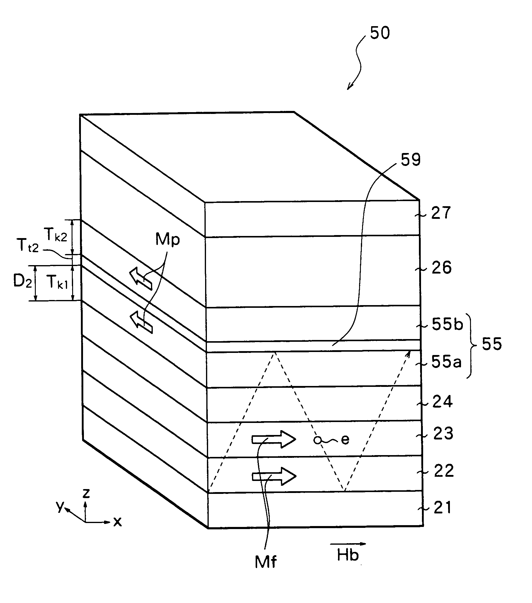
[0134]FIG. 18 shows the structure of the stack 60 of this embodiment. The stack 60 has the same structure as the stack 20 of the first embodiment except that a ferromagnetic layer 65 further includes a ferromagnetic interlayer 69. The ferromagnetic layer 65 and the ferromagnetic interlayer 69 have the same structure as the ferromagnetic layer 55 and the ferromagnetic interlayer 59 of the second embodiment. That is, in this embodiment, when the sense current flows through the stack 60, the route for the electrons e is narrowed by the soft magnetic interlayer 28 and the ferromagnetic interlayer 69, whereby the rate of resistance cha...

examples 1 to 10

[0137]The stacks 20 were prepared as examples 1 to 10. As shown in FIG. 7, each stack 20 has the stacked structure comprising the underlying layer 21, the first lower layer 22a, the soft magnetic interlayer 28, the first upper layer 22b, the second soft magnetic layer 23, the nonmagnetic layer 24, the ferromagnetic layer 25, the antiferromagnetic layer 26 and the protective layer 27, these layers being stacked in sequence on an insulating substrate. First, the underlying layer 21 of 5 nm thick was deposited on the insulating substrate by using Ta by sputtering. The first lower layer 22a was deposited on the underlying layer 21 by using NiFe with varying thickness in accordance with the examples. In the deposition, the first lower layer 22a was deposited in previous consideration of the thickness to be oxidized by the following oxidation so that the thickness Tn1a of the first lower layer 22a might take on values shown in Table 1 after the following oxidation.

[0138]

TABLE 1Thickness (...

examples 11 to 14

[0146]The stacks 20 were prepared as examples 11 to 14 under the same condition as the condition for the example 10, except that the thickness Tt1 of the soft magnetic interlayer 28 was changed as shown in Table 1. The properties of these stacks 20 were examined in the same manner as the example 10. The results are shown in Table 2.

[0147]As can be seen from Table 2, the following tendency was exhibited. In the example 10 in which the thickness Tt1 of the soft magnetic interlayer 28 was 0.6 nm, the highest rate of resistance change was obtained, and the rate of resistance change was reduced regardless of whether the thickness Tt1 was reduced or increased. Moreover, there was shown a tendency that the coercive force Hc was increased when the thickness Tt1 of the soft magnetic interlayer 28 was increased. That is, it turned out that the thickness Tt1 of the soft magnetic interlayer 28 is from 0.5 nm to 1 nm inclusive, whereby the rate of resistance change can be further increased while...


PUM

PropertyMeasurementUnit
thicknessaaaaaaaaaa
distanceaaaaaaaaaa
coercive forceaaaaaaaaaa

Abstract

Provided are a magnetic transducer capable of increasing a resistance change and obtaining an appropriate coercive force, a thin film magnetic head, a method of manufacturing a magnetic transducer and a method of manufacturing a thin film magnetic head.
A stack, a spin valve film has a stacked structure comprising a first soft magnetic layer, a second soft magnetic layer, a nonmagnetic metal layer, a ferromagnetic layer, an antiferromagnetic layer and a protective layer which are stacked in sequence on an underlying layer. Electrical resistance is changed in accordance with a relative angle between the orientation of magnetization of the ferromagnetic layer and the orientation of magnetization of the first and second soft magnetic layers. A soft magnetic interlayer having magnetism and the electrical resistance higher than the electrical resistance of the first soft magnetic layer is formed in the first soft magnetic layer. When a current flows through the stack, electrons are reflected by the surface of the soft magnetic interlayer and thus a path for the electrons is narrowed. Therefore, a rate of resistance change is increased.

Description

[0001]This application is a Divisional of U.S. application Ser. No. 09 / 425,967 filed on Oct. 25, 1999, now U.S. Pat. No. 6,661,623 the contents of which are incorporated herein in its entirety.BACKGROUND OF THE INVENTION[0002]1. Field of the Invention[0003]The invention relates to a magnetic transducer, a thin film magnetic head using the same, a method of manufacturing a magnetic transducer and a method of manufacturing a thin film magnetic head. More particularly, the invention relates to a magnetic transducer capable of obtaining the more excellent rate of resistance change, a thin film magnetic head and a method of manufacturing the same.[0004]2. Description of the Related Art[0005]Recently, an improvement in performance of a thin film magnetic head has been sought in accordance with an increase in a surface recording density of a hard disk or the like. A composite thin film magnetic head, which has a stacked structure comprising a reproducing head having a magnetoresistive effe...

Claims


Application Information

Patent Timeline
Patent Type & Authority Patents(United States)
IPC IPC(8): G11B5/39G11B5/31
CPCB82Y10/00B82Y25/00G11B5/3903G11B5/313G11B2005/3996
Inventor TSUCHIYA, YOSHIHIROARAKI, SATORUSANO, MASASHI
Owner TDK CORPARATION
Why Eureka
Try Eureka