
Harmonic drive type high-accuracy position control system and method

A technology of harmonic drive and control system, applied in the direction of control using feedback, can solve problems such as increasing active damping, and achieve the effect of simple control method and convenient debugging

Active Publication Date: 2014-09-24
INST OF OPTICS & ELECTRONICS - CHINESE ACAD OF SCI
View PDF4 Cites 17 Cited by
  • Summary
  • Abstract
  • Description
  • Claims
  • Application Information

AI Technical Summary

Problems solved by technology

For example, in the article "Research on Harmonic Drive System Based on Acceleration Sensor Feedback Control" by Qiu Zhicheng and others ("China Mechanical Engineering", 2000, Vol. 11, No. 11, pp. 1201-1205), in order to suppress the flexibility, Due to the vibration caused by nonlinear friction and other factors to the load, a feedback control based on the acceleration sensor is proposed, which increases the active damping of the system to suppress the nonlinear disturbance of the system, but this method needs to introduce an accelerometer to measure the acceleration of the load

Method used


Image

  • Harmonic drive type high-accuracy position control system and method
  • Harmonic drive type high-accuracy position control system and method
  • Harmonic drive type high-accuracy position control system and method

Examples


Embodiment Construction

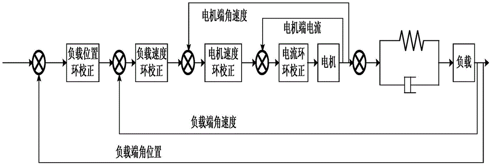
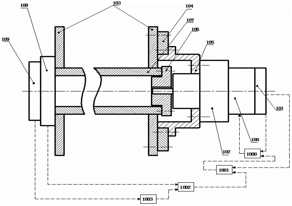
[0043] Such as figure 1 As shown, the control objects of the system include DC brushless motor 100, harmonic reducer 102 and load 107, and the harmonic reducer is simplified as a spring-damper system, so the control object can be regarded as two masses connected by spring damping system. The innermost loop to the outermost loop of the system are respectively the motor-side current loop, the motor-side speed loop, the load-side speed loop and the load-side position loop. The current of the motor is detected by the internal detection device of the motor driver 110 , and the speed of the motor is obtained by differentiating the position signal detected by the rotary encoder 101 at the motor end. The speed and position information of the load end can be obtained by the tachometer 108 and the photoelectric encoder 109 respectively.

[0044] The first step: system installation and connection. In order to avoid the loss of stiffness caused by the couplings as much as possible, the...


PUM


Abstract

The invention relates to a harmonic drive type high-accuracy position control system and method. For the nonlinear dead zone characteristic caused by harmonic drive flexibility, the system and method of the invention adopt a control structure in which a current loop sleeves a dual velocity loop and then sleeves a position loop, so the dead zone characteristic in system tracking control can be restrained, and the tracking control accuracy can be improved. The control method mainly utilizes the advantage that multiple closed-loops exist in the output feedback, the current loop is adopted to increase the stationarity of the output force moment, the position measured by a rotary encoder is utilized to decouple the rotating speed of the motor rotor to form a speed closed-loop of the motor end, the nonlinear characteristics, such as the flexibility, the friction, etc., of a harmonic reducer are isolated in advance, and the motor anti-interference capability can be enhanced. Then, accurate control is performed on the load by combining with the outer speed loop formed by a speed measuring device and a photoelectric encoder and the position loop at the load end. Compared with the existing harmonic drive type high-accuracy control technologies, advantages of high accuracy, simple control structure and convenient debugging can be realized.

Description

technical field [0001] The invention belongs to the field of high-precision servo control of harmonic drives, and in particular relates to a high-precision control system and method of a harmonic reducer in a photoelectric tracking system. The harmonic reducer belongs to the flexible gear transmission, so the platform with the harmonic reducer will inevitably be affected by the nonlinearity brought by the transmission gap and flexibility, which is mainly manifested as a dead zone phenomenon. The invention helps to suppress the non-linear characteristics of the dead zone caused by gaps and flexibility, and improves the tracking accuracy of the servo system. technical background [0002] Harmonic transmission is a transmission technology developed rapidly in the 1980s and 1990s. It stands out among various reducer transmissions with its advantages of small size, light weight, large transmission ratio and small transmission gap. It uses the difference in the number of teeth be...

Claims


Application Information

Patent Timeline
Patent Type & Authority Applications(China)
IPC IPC(8): G05D3/12
Inventor 黄永梅蔡华祥杜俊峰唐涛张桐付承毓
Owner INST OF OPTICS & ELECTRONICS - CHINESE ACAD OF SCI
Learn More