Combined clamp assembly optimizing method based on assembly dimension path diagram

A technology of combined fixture and assembly size, applied in special data processing applications, instruments, electrical digital data processing, etc., can solve the problem of difficult to clearly display the assembly of combined fixtures, and achieve the effect of good representation

Inactive Publication Date: 2014-09-24
TAIYUAN UNIVERSITY OF SCIENCE AND TECHNOLOGY
View PDF3 Cites 9 Cited by
  • Summary
  • Abstract
  • Description
  • Claims
  • Application Information

AI Technical Summary

Problems solved by technology

[0003] In the prior art, the 3D assembly model can generally only be applied to the combination fixture with a relatively simple structure; it is difficult to clearly show the assembly condition of the combination fixture in the 2D diagram

Method used


Image

  • Combined clamp assembly optimizing method based on assembly dimension path diagram
  • Combined clamp assembly optimizing method based on assembly dimension path diagram
  • Combined clamp assembly optimizing method based on assembly dimension path diagram

Examples


Embodiment Construction

[0031] The above and other technical features and advantages of the present invention will be described in more detail below in conjunction with the accompanying drawings.

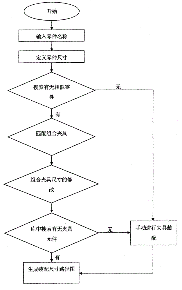
[0032] see figure 1 As shown, the specific process of the present invention's combined fixture assembly optimization method based on the assembly dimension path diagram is:

[0033] Step a, labeling of combined fixture components;

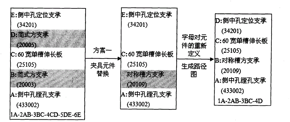
[0034] Use English letters in order from bottom to top, or from left to right to represent the fixture components in the combined fixture.

[0035] Each component in the component library is represented by an English letter, and the surface of the component is represented by a number plus a letter. The specific number and letter are determined according to the position of the component in the combined fixture. For example, the letter A is used to represent the combined fixture component, 1A and 2A represent the lower surface and the upper surface of the component respectively...


PUM


Abstract

The invention relates to a combined clamp assembly optimizing method based on an assembly dimension path diagram. The specific process comprises the steps as follows: labeling of the elements of a combined clamp, that is, representing the clamp elements of the combined clamp by English letters in sequence from top to bottom or from left to right; automatic assembly of the combined clamp, wherein the process comprises the steps as follows: a user inputs the name or other characteristic attributes of a workpiece; a system starts performing case-based reasoning through the name or other characteristic attributes of the workpiece to search out a highly similar case; the dimensions of the clamp elements are reasonably modified according to the dimension of the processed workpiece, a plurality of schemes are given, the types and quantity of the elements are searched from an element library, whether the types and quantity of the elements meet the requirements of one scheme, if yes, the system gives the final scheme, otherwise, the system automatically eliminates the scheme. The method provided by the invention can effectively improve the assembly efficiency of the combined clamp.

Description

technical field [0001] The invention relates to the field of fixture assembly, in particular to an optimal method for assembling a combined fixture based on an assembly dimension path diagram. Background technique [0002] Computer-aided assembly technology for combination fixtures has been developed for many years. At present, the prior art includes the secondary development of SolidWorks by using Visual Basic, and the hybrid reasoning technology based on rule-based reasoning technology (RBR) and case-based reasoning technology (CBR), and the developed slot system combined fixture CAD system; there is also a CAD system for CAD The combined fixture assembly system invented by secondary development. [0003] In the prior art, the three-dimensional assembly model can generally only be applied to the combination fixture with a relatively simple structure; it is difficult to clearly show the assembly condition of the combination fixture in a two-dimensional drawing. [0004] I...

Claims


Application Information

Patent Timeline
Patent Type & Authority Applications(China)
IPC IPC(8): G06F19/00
Inventor 郭宏杜夏威闫献国张荣彭菲梁晓阳
Owner TAIYUAN UNIVERSITY OF SCIENCE AND TECHNOLOGY
Why Eureka
Try Eureka