Vehicle drive device

A technology of driving device and fluid transmission device, applied in the direction of transmission device, power device, electric power device, etc., can solve the problems of insufficient cooling performance of motor and oil cooling of motor, and achieve thermal conductivity suppression, thermal performance improvement, and cooling performance improvement. Effect

Active Publication Date: 2014-09-24
TOYOTA JIDOSHA KK
View PDF11 Cites 9 Cited by
  • Summary
  • Abstract
  • Description
  • Claims
  • Application Information

AI Technical Summary

Problems solved by technology

Therefore, also in Patent Document 2, it is difficult to cool the motor oil, and there is a possibility that the cooling performance of the motor is insufficient.

Method used


Image

  • Vehicle drive device
  • Vehicle drive device
  • Vehicle drive device

Examples


Embodiment

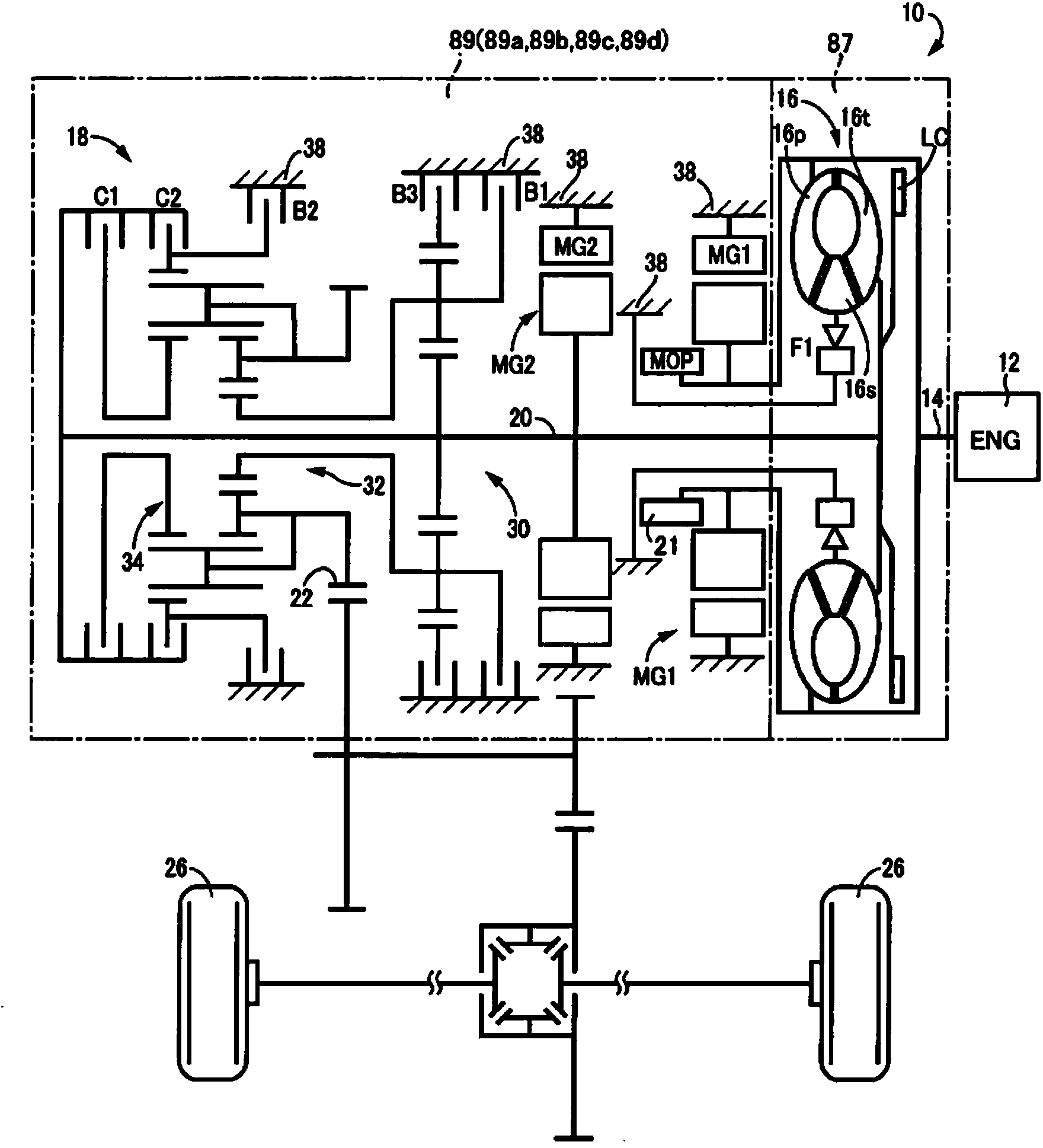
[0024] figure 1 It is a frame diagram illustrating the configuration of a vehicle drive device 10 according to an embodiment of the present invention. exist figure 1 Among them, the drive device 10 for a vehicle is suitable for use in an FF (front engine, front drive) type vehicle, and has an engine 12 functioning as a prime mover, a torque converter 16 connected to a crankshaft 14 of the engine 12, and a set Between the torque converter 16 and the drive wheels 26 and connected to the output side of the torque converter 16 (and the fluid transmission device of the present invention), the automatic transmission 18 is arranged and connected between the torque converter 16 and the automatic transmission 18 The first electric motor MG1 arranged between the first electric motor MG1 and the automatic transmission 18 and connected to the pump impeller 16p serving as an input-side rotating member of the torque converter 16 and the turbine impeller 16t serving as an output-side rotati...


PUM


Abstract

Provided is the structure of a vehicle drive device provided with a fluid transmission device, an electric motor and a transmission, said vehicle drive device being capable of improving the cooling performance of the electric motor. Even in a configuration in which an engine (12) and a first electric motor (MG1) are linked to a pump impeller (16p) of a torque converter (16), the engine (12) and the first electric motor (MG1) are positioned in a location where the torque converter (16) is sandwiched in the axial direction, thus enabling the first electric motor (MG1) to be positioned in a space (89) (inside an oil chamber) in which an automatic transmission (18) is housed. Moreover, housing the first electric motor (MG1) inside said space (89) allows the first electric motor (MG1) to be cooled by oil, thus enabling the cooling performance of the first electric motor (MG1) to be improved.

Description

technical field [0001] The present invention relates to a fluid transmission device comprising: an input-side rotating member for inputting power from a prime mover; an output-side rotating member for outputting power to drive wheels; an electric motor connected to the input-side rotating member; A structure of a vehicle drive device for a transmission of the above-mentioned output side rotary member. Background technique [0002] There is known a fluid transmission device having an input-side rotating member for inputting power from a prime mover and an output-side rotating member for outputting power to drive wheels, an electric motor connected to the input-side rotating member, and a fluid transmission device connected to the above-mentioned fluid transmission device. A vehicle drive device for a transmission of the above-mentioned output side rotary member. The drive device for a hybrid vehicle disclosed in Patent Document 1 is an example of this. In the drive device f...

Claims


Application Information

Patent Timeline
Patent Type & Authority Applications(China)
IPC IPC(8): B60K6/40B60K6/24B60K6/26B60K6/36B60K6/44B60K6/547B60L50/16
CPCY02T10/6295B60K2001/006B60K6/547B60K6/405B60K2006/4825Y02T10/6243Y02T10/6252B60K6/485B60K6/40Y02T10/6226Y02T10/623Y02T10/6221B60K6/48B60K6/365B60K6/445Y10S903/915Y02T10/62F16H41/00F16H41/02F16H45/00F16H45/02B60K6/26B60K6/36B60K6/383B60K6/50
Inventor 奥田弘一田端淳今村达也今井惠太水篠翔
Owner TOYOTA JIDOSHA KK
Why Eureka
Try Eureka