Bio-electricity signal sensor

A bioelectrical signal and sensor technology, which is applied in the fields of sensors, medical science, diagnostic recording/measurement, etc., can solve the problems of cleaning, troublesome operators, high electrode impedance, etc., and achieve improved measurement signal-to-noise ratio, stable skin impedance, and skin The effect of low impedance

Inactive Publication Date: 2014-10-01
SUZHOU GREENTEK
View PDF1 Cites 21 Cited by
  • Summary
  • Abstract
  • Description
  • Claims
  • Application Information

AI Technical Summary

Problems solved by technology

[0004] 1. Professional medical staff are required to apply conductive glue or conductive paste, which limits the application range of wet electrodes in households, games, etc.; in addition, it takes a long time to apply conductive glue or conductive paste;
[0005] 2. Conductive glue or conductive paste is prone to cracking or falling off after long-term use, resulting in interruption of measurement, and is not suitable for long-term use of EEG rehabilitation equipment;
[0006] 3. The test subjects are often covered with conductive glue or conductive paste. After the test, the test subjects need to wash their hair, which brings discomfort to the test subjects
In addition, the operator needs to

Method used


Image

  • Bio-electricity signal sensor
  • Bio-electricity signal sensor
  • Bio-electricity signal sensor

Examples


Embodiment 1

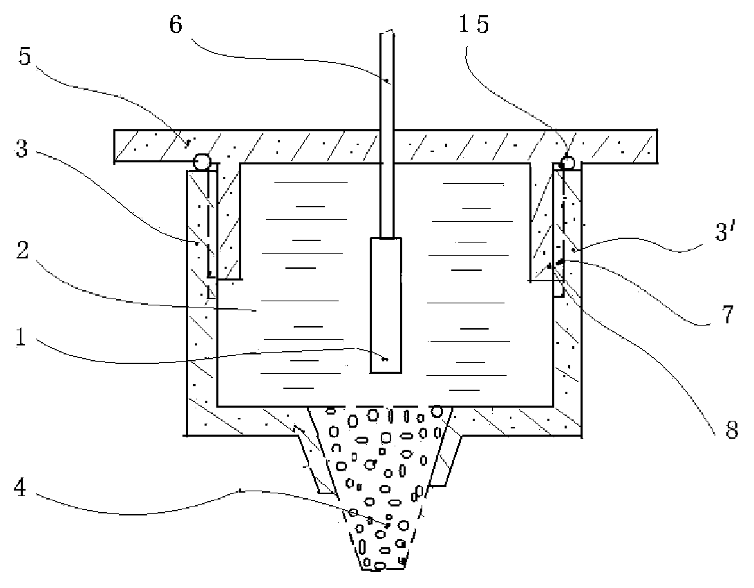
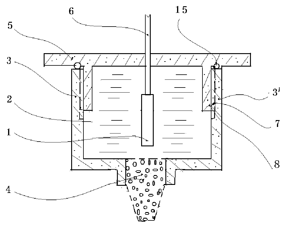
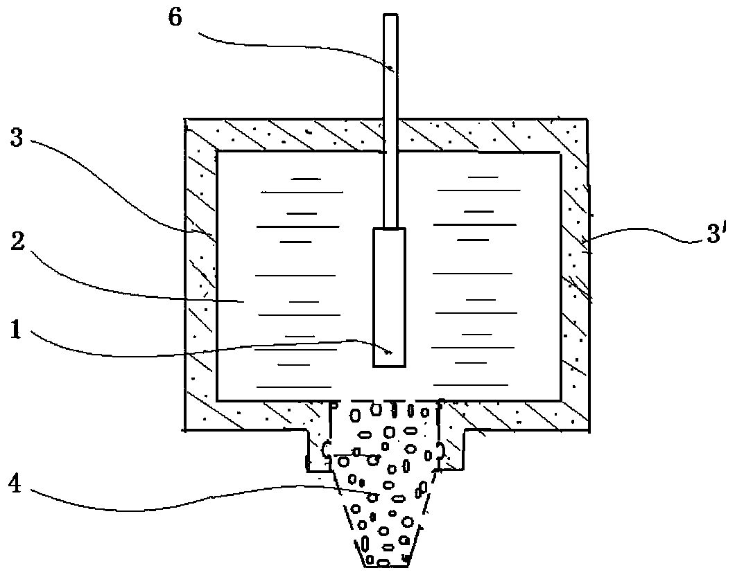
[0050] Embodiment 1: It is the basic embodiment of the bioelectrical signal sensor of the present invention. As shown in the figure, a bioelectrical signal sensor includes an electrode 1, an electrolyte 2, a cavity 3 capable of accommodating the electrolyte, and a porous column 4; one end of the cavity 3 is a sealed end, and the other end is connected to the porous column 4 The electrolyte entry end is connected, and the other end of the porous column 4 is the working end in contact with the organism; at least a part of the electrode 1 is immersed in the electrolyte 2; the electrode 1 is a conductor, and the cavity 3 is a conductor or insulator.

Embodiment 2

[0051] Embodiment 2: is the further embodiment of embodiment 1. like Figure 1-10 As shown, the bioelectric signal sensor has one porous column. The number of porous columns can also be multiple, such as Figure 11 , 12 , 13 shown. The porous columns are evenly distributed on the end surface of the cavity 3 with the centroid of the cavity end surface as the center, or the porous columns can be evenly distributed side by side on the end surface of the cavity. The porous column adopts multiple porous columns on the end face of the cavity, and the electrolyte that seeps through the capillary of each porous column establishes a good ion channel with the electrode and conducts conduction with the electrode. The measured bioelectrical signal is equivalent to the addition of a single porous column. And, the measurement signal quality is good. In the bioelectrical signal sensor, the porous column 4 is made of porous ceramic material or a composite material of porous ceramic. Por...

Embodiment 3

[0053] Embodiment 3: is the further embodiment of embodiment 1. like figure 1 As shown, in the bioelectrical signal sensor, the sealing end of the cavity 3 is a sealing cover 5, and the sealing cover 5 is connected to the body 3' of the cavity 3 in a detachable sealed and fixed connection, as shown in FIG. figure 1 , 2 , 5, 6, 7, and 11, the sealing cover 5 is threadedly connected to the body 3' of the cavity 3; the electrolyte inlet end of the porous column 4 is fixedly connected to the mounting hole on the end face of the cavity 3, and this implementation For example, the electrolyte inlet end of the porous column 4 is connected to the installation hole on the end surface of the cavity 3 by injection molding.

[0054] The electrolyte inlet end of the porous column 4 is connected to the installation hole on the end face of the cavity body 3, and there are also equivalent embodiments, such as figure 2 As shown, the electrolyte entry end of the porous column 4 is cylindrica...


PUM


Abstract

The invention relates to a bio-electricity signal sensor. The bio-electricity signal sensor comprises an electrode, an electrolyte, a cavity capable of holding the electrolyte, and a porous column, wherein one end of the cavity is a sealed end, and the other end of the cavity is connected with an electrolyte entering end, and another end of the porous column is a working end in contact with a living body; at least a part of electrode is located in the electrolyte, the electrode is a conductor, and the cavity is either a conductor or an insulator. The bio-electricity signal sensor provided by the invention has the main advantages of being simple in structure, reliable to contact, precise to locate, low and stable in electrode-skin impedance, low in noise measurement, low in artifact and convenient and comfortable to use, and is capable of recycling for a long time, thereby being applicable to relevant applications of bioelectricity recording, measuring and stimulation, and particularly applicable to electroencephalogram measurement.

Description

technical field [0001] The invention relates to a bioelectrical signal sensor, which belongs to the technical field of bioelectricity and is widely used in bioelectricity recording, measurement and stimulation, including high-density electrode measurement, medical equipment, mobile equipment, home health care, psychological cognition, games, brain-computer interface, Rehabilitation training, etc., especially suitable for EEG measurement. Background technique [0002] With the development of science and technology, bioelectricity has been widely used in the monitoring and diagnosis of various nervous system diseases, as well as rehabilitation equipment for bioelectrical feedback. Bioelectricity measurement is also an important experimental method in the study of cognitive psychology. The EEG signal is a very weak bioelectrical signal, generally at the microvolt level. Accurate acquisition of EEG signals requires sophisticated and reliable equipment systems. EEG measurement ...

Claims


Application Information

Patent Timeline
IPC IPC(8): A61B5/0478A61B5/04
CPCA61B5/6803A61B5/24A61B5/291A61B2562/168A61B2562/0217A61B2562/0215A61B5/263
Inventor 樊安生
Owner SUZHOU GREENTEK
Why Eureka
Try Eureka