Combined cutting tool and processing method for processing holes
A technology of combining cutting tools and processing methods, applied in manufacturing tools, metal processing equipment, drilling tool accessories, etc., can solve the problems of low precision and cumbersome operation of adjusting the position of the cutting edge, so as to improve processing efficiency, simple and easy to expand. Hole processing, the effect of improving the service life
- Summary
- Abstract
- Description
- Claims
- Application Information
AI Technical Summary
Problems solved by technology
Method used
Image
Examples
Embodiment 1
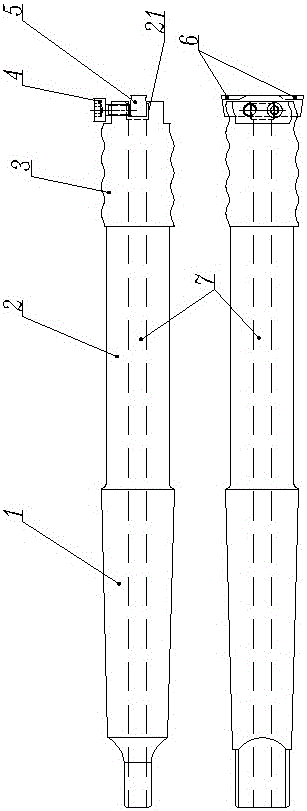
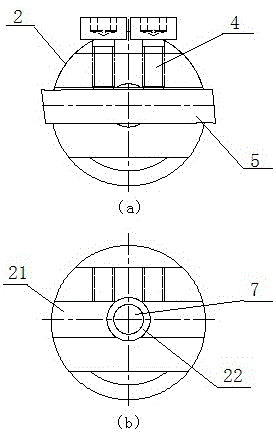
[0027] like figure 1 As shown, a combination tool for machining holes includes a tool holder 2 and a cutter head 5, and one end of the tool holder 2 is a Morse taper 1 structure, through which the combination tool can be inserted into the Morse taper of a lathe tailstock or a drilling fixture. There is a square groove 21 at the top of the other end of the cutter bar 2, and the cutter head 5 can be loaded in the square groove, and the cutter head 5 is fastened with two screws 4. The end of the cutter head 5 There is a chip breaker 6 on both sides of the head; there is a through hole 7 in the middle of the tool bar 2, and the coolant can enter from the through hole 7 when machining deep holes. Since the tool rod is relatively slender, in order to ensure the rigidity of the tool rod, the diameter of the through hole 7 cannot be too large. During processing, we found that the diameter of the through hole 7 is slightly smaller than the height of the cutter head 5, so that when the ...
Embodiment 2
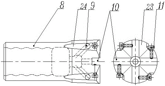
[0030] like image 3 , Figure 4 As shown, the second combination tool for machining holes includes a cutter bar 2 and a cutter head body 8 installed on the cutter bar 2. The cutter bar 2 is provided with a through hole along the axial direction, and one end of the tool bar 2 has a Morse taper. There is a wave thread 3 on the outer surface of the handle 1 and the other end (the wave thread here is only a specific example of thread, as long as it is a thread structure that can form a mating connection, it may be applied in this technical solution by those skilled in the art) , the cutter head body 8 has an internal thread that matches the external thread of the cutter bar 2, and the top of the cutter head body 2 has a cross groove 10, and a small cutter head 12 is respectively installed in the four groove bodies of the cross groove 10, and the knife The number of heads 12 is four, which realizes the participation of multiple cutters and multiple blades in the cutting process, ...
Embodiment 3
[0034] In the utility model patent "a drilling jig for lathes" (ZL20072 0144284.7) that the inventor applied for and obtained authorization in 2007, a drilling jig for lathes is disclosed, such as Figure 5 As shown, including the clamp body 13, there is a Morse taper hole 16 on the clamp body, and the Morse taper hole 16 is provided with an opening slit 15 to the edge of the clamp body 13, and the Morse taper hole taper hole side of the clamp body is perpendicular to the opening Two screw holes 14 are arranged at intervals in the seam direction, and a clamp screw 17 is installed in the screw holes, and a washer 18 is arranged between the clamp screw 17 and the clamp body 13 .
[0035]The two combination cutters proposed by the present invention can be used in conjunction with the above-mentioned clamps. The processing method of the first cutter is: place the clamp body 13 flatly against the lathe tool holder 20, tighten the tool holder screw rod 19, and place the cutter head 5...
PUM
| Property | Measurement | Unit |
|---|---|---|
| hardness | aaaaa | aaaaa |
Abstract
Description
Claims
Application Information
 - R&D
- Intellectual Property
- Life Sciences
- Materials
- Tech Scout
- Unparalleled Data Quality
- Higher Quality Content
- 60% Fewer Hallucinations
Browse by: Latest US Patents, China's latest patents, Technical Efficacy Thesaurus, Application Domain, Technology Topic, Popular Technical Reports.
© 2025 PatSnap. All rights reserved.Legal|Privacy policy|Modern Slavery Act Transparency Statement|Sitemap|About US| Contact US: help@patsnap.com


