
Automatic calibration system for remote-measuring equipment

A technology of telemetry equipment and calibration system, applied in the direction of instruments, etc., can solve the problems of large impact on test accuracy, complex test process, calibration and other problems, and achieve the effect of eliminating data filling errors, improving test efficiency and high test accuracy.

Active Publication Date: 2014-10-01
NANJING UNIV OF AERONAUTICS & ASTRONAUTICS
View PDF5 Cites 13 Cited by
  • Summary
  • Abstract
  • Description
  • Claims
  • Application Information

AI Technical Summary

Problems solved by technology

[0002] At present, domestic telemetry equipment development and production units all use manual or semi-automatic methods for testing. This test method has been unable to meet the testing requirements of increasingly complex telemetry systems, specifically reflected in the following problems:
The testing process is very complicated, and it takes several hours for 2-3 testers to complete the complete test
[0004] 2) Multiple personnel are often required to perform division of labor testing. Each tester must master the direct or indirect measurement methods of various signal parameters, and interpret and manually record various measurement results. The accuracy of the test is greatly affected by human factors, and it is difficult to form standardized testing;
[0005] 3) It is impossible to calibrate the transmission coefficient of the telemetry channel, and only theoretical estimates can be used according to the hardware circuit design
Since the differences between different batches of telemetry cabins and different telemetry channels are not considered, the test results of the transmission accuracy of each telemetry channel are not realistic and accurate enough

Method used


Image

  • Automatic calibration system for remote-measuring equipment
  • Automatic calibration system for remote-measuring equipment
  • Automatic calibration system for remote-measuring equipment

Examples


Embodiment Construction

[0042] The present invention will be further described below in conjunction with the accompanying drawings.

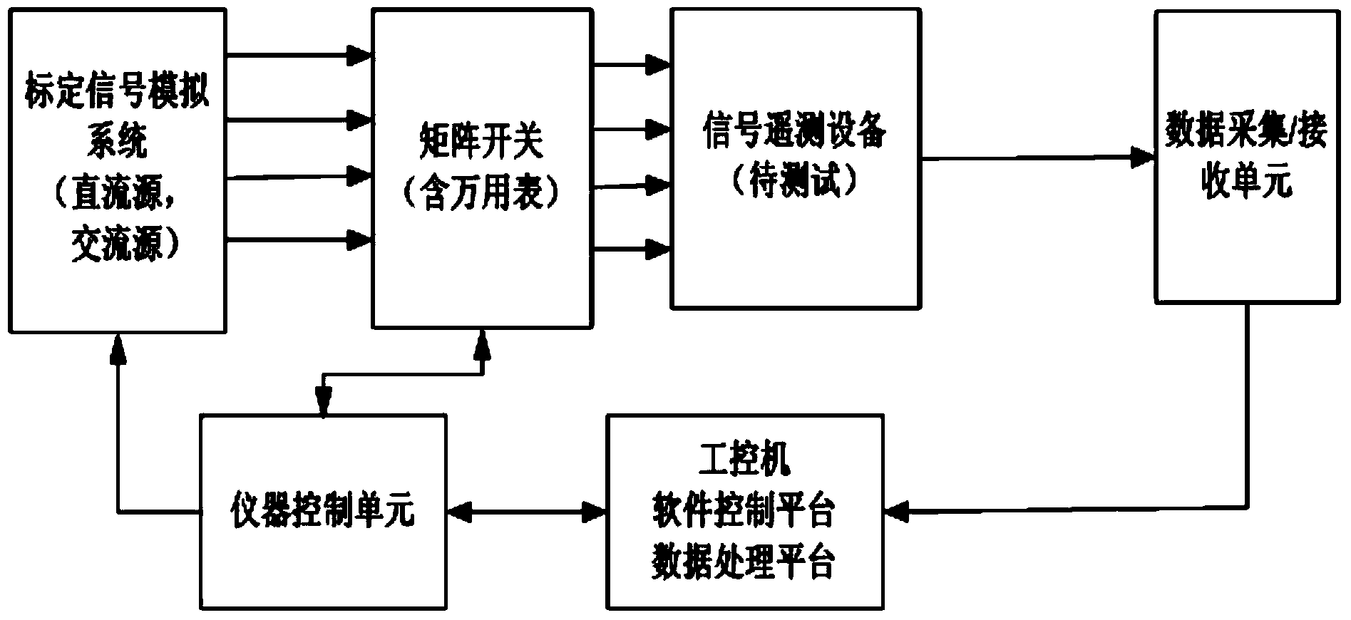
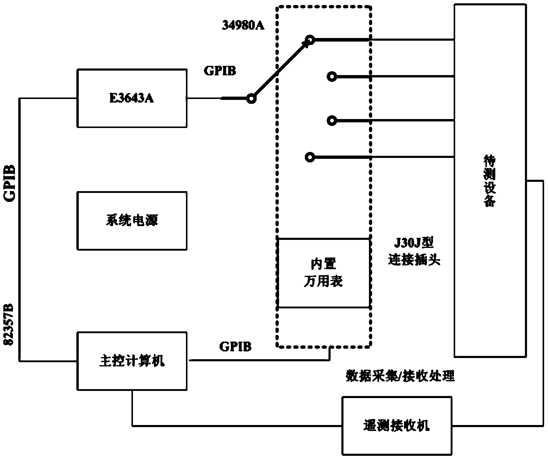
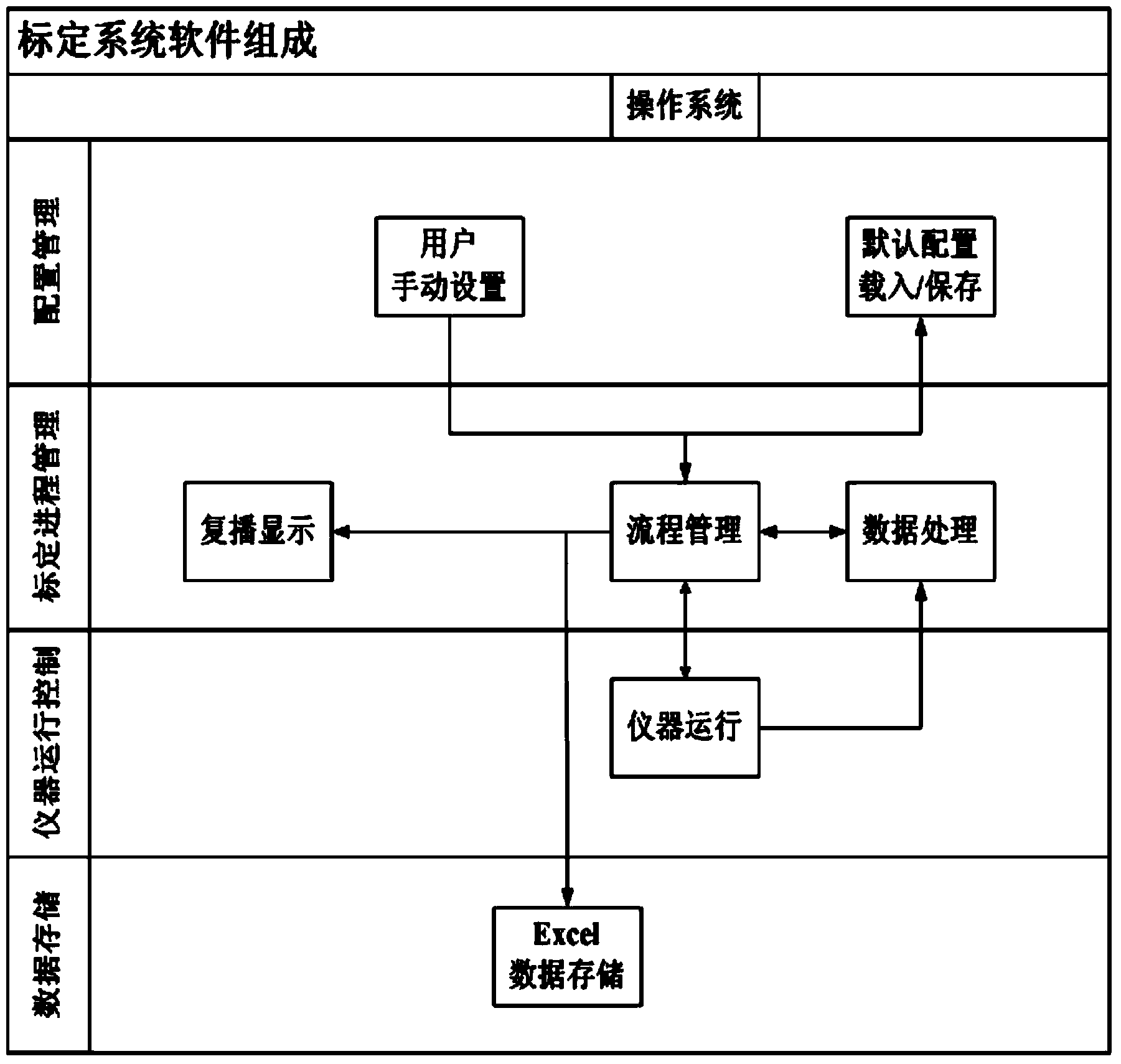
[0043] An automatic calibration system for telemetry equipment, such as Figure 1-4 shown, including:

[0044] Human-computer interaction interface, the human-computer interaction interface is used for the input of user parameters, and the user parameters are transmitted to the software control platform, and the user parameters include the setting of the channel to be tested, the setting of the mode to be tested, the calibration mode and the Set the signal source required by the measurement channel;

[0045] Calibration signal simulation system, the calibration signal simulation system is used to generate a corresponding reference signal according to the signal source parameters and calibration mode required by the channel to be tested received from the instrument control unit, and the reference signal is connected to the signal telemetry through the matrix switch Th...


PUM


Abstract

The invention discloses an automatic calibration system for remote-measuring equipment, and belongs to the testing technology of the remote-measuring equipment. The automatic calibration system comprises a human-computer interaction interface, a calibration signal analog system, a matrix switch, the signal remote-measuring equipment, a data collection / reception unit, an instrument control unit, a data processing platform and a software control platform. The automatic calibration system estimates output signals through the data analyzing and processing method. The output signals and reference signals input by the calibration signal analog system are compared, fitting of a transmission curve is carried out, a system transfer function and transmission accuracy are calculated, and a data table is generated to record transmission data and a characteristic function of each channel. The automatic calibration system can test transmission factors of direct current signal channels and alternating current signal channels automatically according to the user requirements, and can be used for testing the transmission factors of the channels of the remote-measuring equipment of different types fast and accurately on the basis of a virtual instrument platform, obtain a transmission channel model of the equipment to be tested visually and clearly, and provide the basis for correction of the transmission channels of the remote-measuring equipment under different external environments.

Description

technical field [0001] The invention relates to an automatic calibration system for remote measurement equipment based on the LabWindows / CVI software platform, belonging to the remote measurement equipment testing technology. Background technique [0002] At present, domestic telemetry equipment development and production units all use manual or semi-automatic methods for testing. This test method has been unable to meet the testing requirements of increasingly complex telemetry systems, specifically reflected in the following problems: [0003] 1) It is only suitable for the test of simple telemetry equipment with few telemetry signal channels, few types and low transmission accuracy requirements. The testing process is very complicated, and it will take several hours for 2-3 testers to complete a complete test. [0004] 2) Multiple personnel are often required to perform division of labor testing. Each tester must master the direct or indirect measurement methods of vario...

Claims


Application Information

Patent Timeline
IPC IPC(8): G01D18/00
Inventor 许梁津王成华朱秋明
Owner NANJING UNIV OF AERONAUTICS & ASTRONAUTICS
Learn More