Band-gap reference source for digital-analog hybrid circuit

A digital-analog hybrid and reference source technology, which is applied in the direction of adjusting electrical variables, control/regulation systems, instruments, etc., can solve problems such as limiting power supply voltage, increasing static power consumption and chip area, and affecting the output signal quality of reference voltage sources. Achieve the effects of reducing interference, optimizing load regulation, and improving circuit characteristics

Inactive Publication Date: 2014-10-01
周国文
View PDF6 Cites 14 Cited by
  • Summary
  • Abstract
  • Description
  • Claims
  • Application Information

AI Technical Summary

Problems solved by technology

The traditional bandgap reference source needs to use the feedback loop formed by the operational amplifier to realize the stable output of the voltage reference source. Due to the limitation of the bandwidth and gain of the operational amplifier itself, the fluctuation of the power supply voltage cannot be achieved within a certain bandwidth range (especially in the middle frequency band). is well suppressed, thereby affecting the output signal quality of the reference voltage source
In addition, in the traditional bandgap reference circuit, the output voltage VBE is about 1.25V, which limits the application of the power supply voltage below 1V
The subsequent improved enhanced bandgap reference source circuit structure uses a pre-voltage source to supply power to the bandgap reference source alone, which improves the power supply voltage rejection ratio to a certain extent, but the improved circuit structure increases static power consumption and chip area.
[0005] In addition, there are other deficiencies in existing digital-analog hybrid circuits, which need to be optimized to improve performance

Method used


Image

  • Band-gap reference source for digital-analog hybrid circuit
  • Band-gap reference source for digital-analog hybrid circuit
  • Band-gap reference source for digital-analog hybrid circuit

Examples


Embodiment Construction

[0022] In the following description, numerous specific details are set forth in order to provide a thorough understanding of the present invention. However, the present invention can be implemented in many other ways different from those described here, and those skilled in the art can make similar extensions without violating the connotation of the present invention, so the present invention is not limited by the specific embodiments disclosed below.

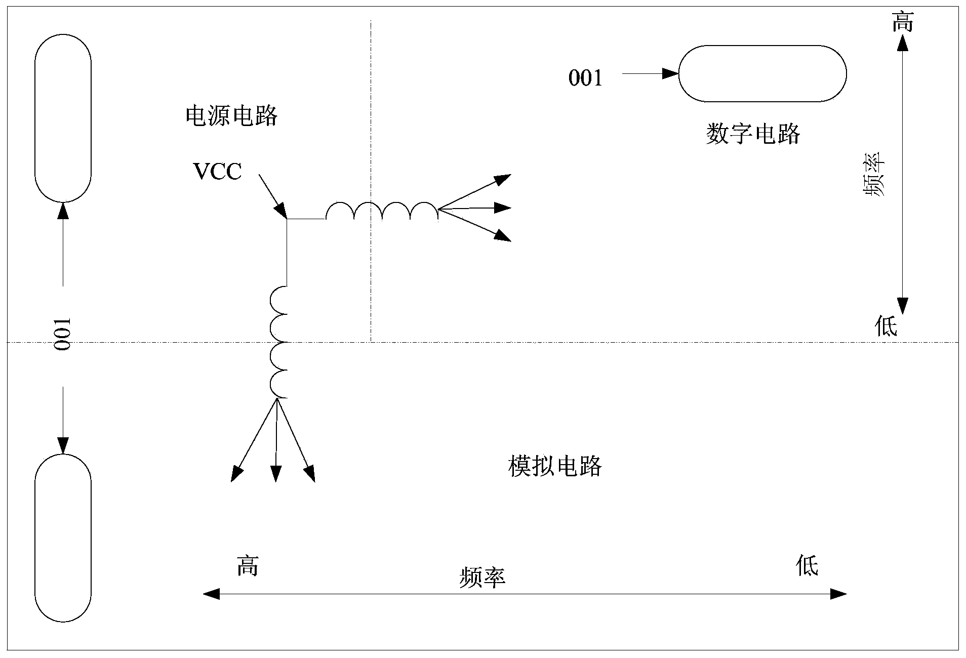
[0023] see figure 1 , is a block diagram of a digital-analog hybrid circuit according to an embodiment of the present invention. This embodiment shows a reasonable layout of the digital-analog hybrid circuit. The digital-analog hybrid circuit includes a power supply circuit (including a reference source), a digital circuit (such as a linear digital power supply circuit, a clock circuit, a DSP device, a CPLD device and an FPGA device) and an analog circuit (such as a digital-to-analog converter, an analog-to-digital converter) ...


PUM


Abstract

The invention discloses a band-gap reference source for a digital-analog hybrid circuit. The configuration of the band-gap reference source is that a source electrode of an MOS pipe M18 and a source electrode of an MOS pipe M19 are both connected with a power supply; a gate electrode of the MOS pipe M18 and a gate electrode of the MOS pipe M19 are both connected with the output terminal of an amplifier IC; a drain electrode of the MOS pipe M18 is connected with one input terminal of the amplifier IC through a resistor R2; a drain electrode of the MOS pipe M19 is connected with the other input terminal of the amplifier IC through a resistor R3; the resistor R2 is connected to a collecting electrode of a triode Q1; the collecting electrode of the triode Q1 is connected with a base electrode of the triode Q1; an emitting electrode of the triode Q1 is earthed; the resistor R3 is connected to a collecting electrode of a triode Q2 through a resistor R4; the collecting electrode of the triode Q2 is connected with a base electrode of the triode Q2; an emitting electrode of the triode Q2 is earthed. The band-gap reference source can improve the performances in a certain aspect of reducing interference of power wires and earth wires, realizing the high rejection ratio of the power supply voltage, improving working stability, or optimizing the load regulation.

Description

technical field [0001] The invention relates to integrated circuit design technology, in particular to a digital-analog hybrid circuit (chip) and its auxiliary circuits. Background technique [0002] At present, digital-analog hybrid circuits are more and more widely used. Due to the existence of digital circuits and analog circuits at the same time, many factors must be considered during design. Here are some examples: [0003] One is that the grounding should be reasonable. In the digital-analog hybrid circuit, the digital signal is a noise source of the analog signal, which will bring ground bounce noise and power disturbance to the entire circuit. These noises and interferences are coupled into the analog circuit, which will affect the working performance of the analog circuit. Since most of the interference sources are generated through the ground wire and the power wire, and the noise interference caused by the ground wire is the largest, the design of the ground wi...

Claims


Application Information

Patent Timeline
Patent Type & Authority Applications(China)
IPC IPC(8): G05F3/26
Inventor 周磊
Owner 周国文
Why Eureka
Try Eureka